Supercharge Your Innovation With Domain-Expert AI Agents!

Chassis structure of electric automobile

A technology for electric vehicles and chassis, applied in the direction of structural parts, circuits, electrical components, etc., can solve the problems of complex maintenance operations, inconvenient disassembly and maintenance of battery modules, and unsuitable for production lines.

Inactive Publication Date: 2018-02-23
OPTIMUM BATTERY CO LTD
View PDF5 Cites 3 Cited by
  • Summary
  • Abstract
  • Description
  • Claims
  • Application Information

AI Technical Summary

Problems solved by technology

[0003] The existing electric vehicle chassis mainly removes the traditional power system such as the engine on the traditional vehicle chassis, and mounts the battery box with the battery on it, and the connection of the single battery in the battery module in the battery box mainly consists of bolt connection and welding. Bolt connection is to screw the single battery to the manifold. This kind of battery module has a large number of manifolds. The positive and negative directions of each single battery have a strict correspondence with the design of the manifold, and the structure is complex. , the installation is difficult, and the maintenance operation is complicated; welding is mainly divided into resistance welding, laser welding and ultrasonic welding. The cost is also high, it is not suitable for production line assembly, and the disassembly and maintenance of the battery module after welding is also inconvenient

Method used


Image

  • Chassis structure of electric automobile
  • Chassis structure of electric automobile
  • Chassis structure of electric automobile

Examples


Embodiment Construction

[0022] In order to make the object, technical solution and beneficial technical effects of the present invention clearer, the present invention will be further described in detail below in conjunction with the accompanying drawings and specific embodiments. It should be understood that the specific implementations described in this specification are only for explaining the present invention, not for limiting the present invention.

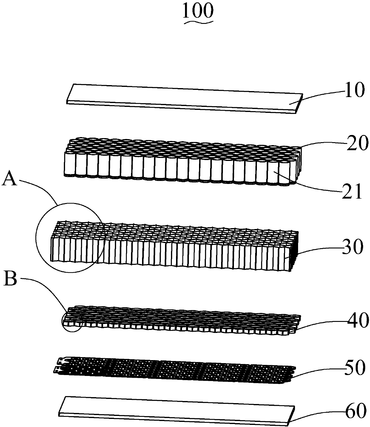
[0023] Such as figure 1 As shown, the present invention provides an electric vehicle chassis structure 100 , including an upper cover 10 , a battery assembly 20 , a honeycomb housing structure 30 , a base assembly 40 , a bus plate 50 and a lower cover 60 .

[0024] Both the upper cover plate 10 and the lower cover plate 60 are made of aluminum alloy through integral machining. The aluminum alloy can be made of light and high-strength aluminum alloy. For example, its composition can be composed of the following raw materials in weight percentage: F...


PUM

PropertyMeasurementUnit
tensile strengthaaaaaaaaaa
thicknessaaaaaaaaaa

Abstract

The invention provides a chassis structure of an electric automobile. The chassis structure of the electric automobile comprises a battery assembly, a honeycomb accommodating structure, a pedestal assembly and a convergence plate; the honeycomb accommodating structure comprises a plurality of hollow honeycomb units; the battery assembly comprises a plurality of single-body batteries; the single-body batteries are accommodated in the honeycomb units; the convergence plate comprises a positive electrode convergence layer and a negative electrode convergence layer positioned on the positive electrode convergence layer; the honeycomb accommodating structure is arranged above the negative electrode convergence layer; a plurality of through holes are formed in the negative electrode convergencelayer; an elastic connecting piece is arranged in each through hole; one end of the elastic connecting piece is connected with the positive electrode convergence layer and the other end of the elasticconnecting piece is connected with a positive electrode contact sheet; the positive electrode of each single-body battery is contacted and electrically connected with the positive electrode contact sheet; the pedestal assembly is accommodated at one end of the honeycomb accommodating structure; the pedestal assembly comprises a plurality of pedestal units; an conductive ring is arranged in the pedestal unit; one end of each single-body battery is inserted in the pedestal unit; and the negative electrode of each single-body battery is connected with the negative electrode convergence layer through the conductive ring.

Description

【Technical field】 [0001] The invention relates to the technical field of electric vehicles, in particular to an electric vehicle chassis structure. 【Background technique】 [0002] Under the pressure of energy crisis and environmental pollution, safety, environmental protection, and energy saving have become the themes of today's automobile development. Electric vehicles have been highly valued and supported by transportation and energy departments due to their advantages in energy saving, environmental protection, and pollution-free. , The new energy vehicle industry ushered in explosive growth. The battery is the core of electric vehicles, and it is also a comprehensive embodiment of automotive engineering and power engineering technology. [0003] The existing electric vehicle chassis mainly removes the traditional power system such as the engine on the traditional vehicle chassis, and mounts the battery box with the battery on it, and the connection of the single battery...

Claims


Application Information

Patent Timeline
Patent Type & Authority Applications(China)
IPC IPC(8): H01M2/20H01M2/10H01M50/244H01M50/249H01M50/505
CPCH01M50/502H01M50/20Y02E60/10
Inventor 段桂林王敬波王哲罗亚炳钟河金
Owner OPTIMUM BATTERY CO LTD
Features
  • R&D
  • Intellectual Property
  • Life Sciences
  • Materials
  • Tech Scout
  • Unparalleled Data Quality
  • Higher Quality Content
  • 60% Fewer Hallucinations
Learn More