Draw welding method for micro-miniature conduction slip ring

A technology of conductive slip ring and welding method, applied in the direction of slip ring manufacturing, circuit, connection, etc., can solve the problems that the strength of solder joints cannot be effectively controlled, the thermal expansion coefficient is inconsistent, and the operating space is small, and it is easy to achieve electrical parameters. Guarantee, improve welding quality, improve the effect of overall performance and reliability

Inactive Publication Date: 2018-02-23
JIUJIANG JINGDA MEASUREMENT TECH
View PDF10 Cites 7 Cited by
  • Summary
  • Abstract
  • Description
  • Claims
  • Application Information

AI Technical Summary

Problems solved by technology

[0003] Due to the small structural size of the miniature conductive slip ring, the outer diameter of the ring piece is Ø6.8mm, the inner diameter is Ø4.4mm, and the thickness is 0.25mm. On this ring piece with a compact structure size, wire welding is required, and due to the narrow operating space, It leads to low welding efficiency (only about 60 pieces of ring pieces can be welded in one day), and at the same time, due to the small welding area, the strength of the solder joints cannot be effectively controlled, which will easily cause false welding of the solder joints, resulting in a large number of defective products and a lot of waste. large, increasing production costs
At the same time, during the vacuum casting process of the welded ring piece, due to the inconsistent thermal expansion coefficients of the epoxy glue and the ring piece, the solder joints on the interface between the epoxy glue and the ring piece are under high and low temperature conditions. There is a risk that the solder joints will fall off to a certain extent, resulting in the failure of a certain loop of the product and the failure of the whole machine.

Method used


Image

  • Draw welding method for micro-miniature conduction slip ring
  • Draw welding method for micro-miniature conduction slip ring
  • Draw welding method for micro-miniature conduction slip ring

Examples


Embodiment Construction

[0030] The present invention will be described in further detail below in conjunction with the embodiments and with reference to the accompanying drawings.

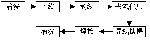
[0031] A hook welding type welding method for a miniature conductive slip ring is characterized in that the specific steps are as follows:

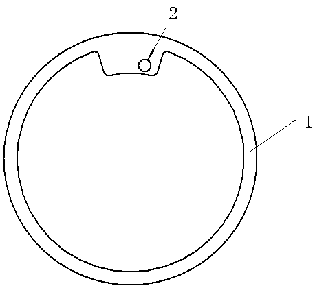
[0032] A. Cleaning: Check the edge burrs and bumps of all rings 1, and deal with them accordingly, and then clean the rings 1 with gasoline;

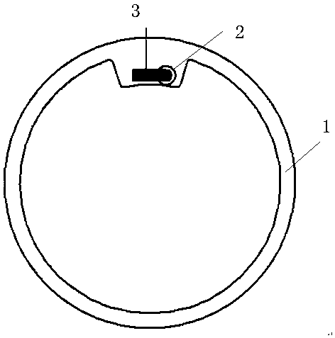
[0033] B. Offline: Offline according to the technical requirements of external components, standard parts summary table and assembly drawing. In order to prevent the impact force from being transmitted to the vulnerable parts, the pliers used for cutting the wire 4 should be particularly sharp, and should be cut along the entire length from beginning to end. The edges are cut with a clean, smooth shear surface; there should be no twisting action during this off-line shearing process;

[0034] C. Wire stripping: use H OT we e z e ts wire therm...


PUM


Abstract

The invention provides a draw welding method for a micro-miniature conduction slip ring. The method includes the steps of cleaning, thread feeding, thread stripping, oxide layer removing, wire tin hotdip coating, welding, cleaning, drying and the like, and then the satisfactory ring piece of wire welding is obtained. The method solves the problem that the welding quality of the micro-miniature conduction slip ring is not good. By using the method, the welding area can be enlarged, the welding quality and reliability of the ring piece can be improved, the intensity of a welding spot can be enhanced, the welding efficiency can be improved, virtual welding phenomena can be avoided at the same time, and the whole performance of the conduction slip ring can be obviously improved. The method further has the advantages of effectively improving the pouring yield of the micro-miniature conduction slip ring, reducing waste and lowering the production cost. The method solves the problem that thewelding quality of the micro-miniature conduction slip ring is not good, and is suitable for the production of the high-accuracy micro-miniature conduction slip ring.

Description

technical field [0001] The invention relates to a welding method, in particular to a hook welding method suitable for the production of high-precision miniature conductive slip rings. Background technique [0002] A conductive slip ring is a device for transmitting electrical power and electrical signals. Its working principle is to realize the precise transmission of electrical signals between the two parts through the relative rotation of the static part and the rotating part of the conductive slip ring. Commonly used in turntable, gyro platform, artillery control, navigation guidance, radar antenna, theodolite and other equipment. [0003] Due to the small structural size of the miniature conductive slip ring, the outer diameter of the ring piece is Ø6.8mm, the inner diameter is Ø4.4mm, and the thickness is 0.25mm. On this ring piece with a compact structure size, wire welding is required, and due to the narrow operating space, It leads to low welding efficiency (only ab...

Claims


Application Information

Patent Timeline
Patent Type & Authority Applications(China)
IPC IPC(8): H01R43/10H01R43/02
CPCH01R43/10H01R43/02
Inventor 王义坚吕斌任梦晴李道权袁仁昆
Owner JIUJIANG JINGDA MEASUREMENT TECH
Why Eureka
Try Eureka