Integral hard alloy A-shaped center drill

A solid carbide and center column technology, which is applied in the direction of center drilling, drill repairing, drilling tool accessories, etc., can solve the problems of insufficient connection strength of the center cone, easy sliding and damage of the drill shank, etc., so as to avoid rotation offset and improve Drilling speed, effect of increasing service life

Inactive Publication Date: 2018-02-27
常州蓝丁格尔工具有限公司
View PDF0 Cites 1 Cited by
  • Summary
  • Abstract
  • Description
  • Claims
  • Application Information

AI Technical Summary

Problems solved by technology

[0003] The traditional A-type center drill, the connection strength of the center cone is not enough, it cannot withstand long-term operation wear, and it is easy to be damaged during use. At the same time, the smooth drill shank is easy to slide during the drilling process, which affects the processing accuracy. It is not easy to estimate the depth when drilling holes with ordinary center drills, and it is inconvenient to control

Method used


Image

  • Integral hard alloy A-shaped center drill
  • Integral hard alloy A-shaped center drill

Examples


Embodiment 1

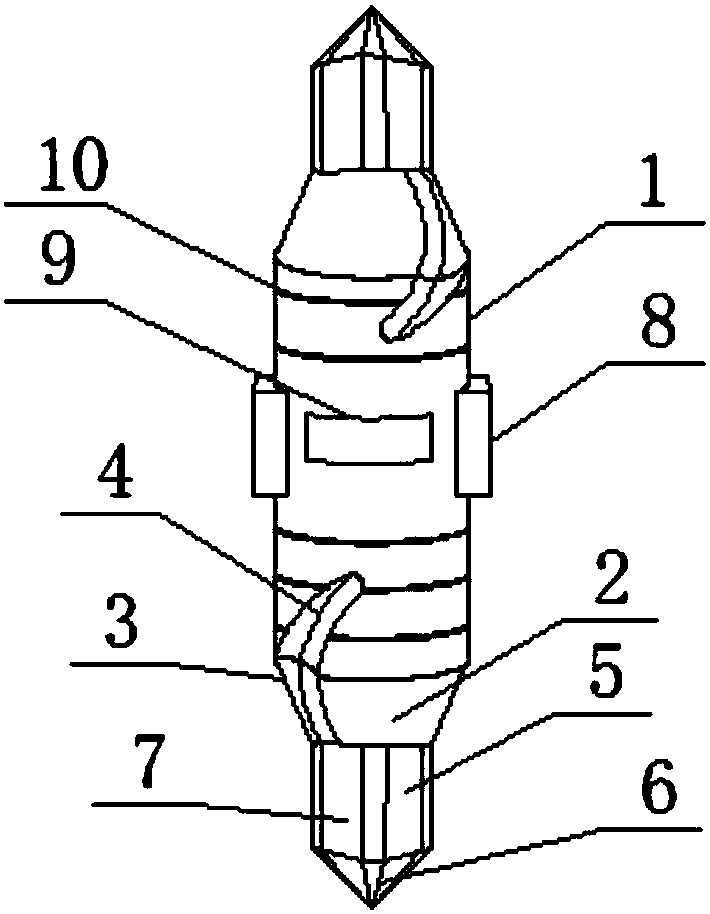
[0019] see figure 1 As shown, a type A center drill of solid carbide includes a drill shank 1, an oblique cutter head 3 and a straight cutter head 6, the two ends of the drill shank 1 are connected to the drill 2, and the double heads on the drill shank 1 are provided with the drill 2, The center drill can be used alternately at both ends to reduce the wear rate of the center drill, increase the service life of the center drill, improve the utilization efficiency of the drill shank 1, and reduce the replacement frequency of the center drill. The inclined groove 4 is set, the inclined cutter head 3 has good mechanical performance, can withstand large shear force, and can cut and mill materials with a large area. The inclined cutter head 3 can increase the drilling rate and reduce the center cone. The chips produced by pressure and processing are exported by the chute 4, the drill bit 2 is connected with the center column 5, and the center column 5 is connected with the straight...

Embodiment 2

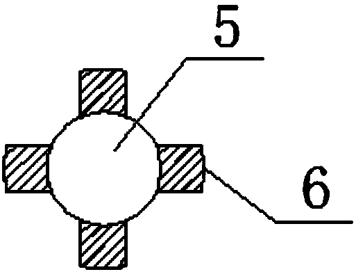
[0021] In addition, refer to figure 1 with figure 2 , based on the above-mentioned embodiment, both ends of the drill shank 1 are provided with drill bits 2, and the drill bit 2 has the same setting, so that the drill shank 1 can improve the utilization rate, and the drill bits 2 can be used alternately, reducing the wear rate of the drill bit 2, and improving the use of the center drill Life, the drill bit 2 is provided with an inclined inclined cutter head 3, one side of the inclined cutter head 3 is higher than the outer diameter of the drill bit 2, so that the inclined cutter head 3 can cut a large area of ​​material, punch a central hole, and increase the rate of drilling. At the same time, the inclined setting allows the inclined cutter head 3 to withstand greater force, and the cutting performance is better. The center column 5 is arranged at the center of the drill bit 2, and the center column 5 is provided with a symmetrical cross-shaped straight cutter head 6, so th...


PUM


Abstract

The invention discloses an A-type central drill of integral hard alloy, which comprises a drill handle, a drill bit, an oblique cutter head, a chute, a central column, a straight cutter head, a straight groove, a clamping block, an identification plate and an identification ring. The main drill shank of the present invention is provided with marking rings, the marking rings are distributed at even intervals, and the marking rings correspond to different depth markings. At the same time, the marking rings are set around, and the marking rings can also grasp the depth well during the rotation of the center drill. , which is conducive to the improvement of the precision of the thread processing process. There are symmetrical blocks on the drill shank, so that the blocks can fix the drill shank, avoiding the rotation deviation of the drill shank during use, and an inclined oblique knife is set on the drill bit. The head can cut and mill large-area materials, and a cross-symmetrical straight cutter head is set on the center column, which can improve the connection strength of the center cone, ensure sufficient strength and wear resistance while increasing the drilling speed, and increase the center drill life.

Description

technical field [0001] The invention relates to a center drill, in particular to an A-type center drill of solid carbide, belonging to the technical field of processing equipment. Background technique [0002] Prefabricated and precise positioning for hole processing, guiding twist drills for hole processing, and reducing errors. The center drill is used for machining the center hole on the end face of parts such as shafts. The product cuts lightly and has good chip removal. There are two types of center drills: Type A: center drill without cone, type B: center drill with cone, when machining a center hole with a diameter of d = 2 ~ 10mm, the center drill without cone is usually used ( Type A); For workpieces with a long process and high precision requirements, in order to avoid damage to the 60-degree centering cone, a center drill with a protective cone (Type B) is generally used. The center hole is the positioning base surface for the shaft workpiece to be installed on...

Claims


Application Information

Patent Timeline
Patent Type & Authority Applications(China)
IPC IPC(8): B23B51/00
CPCB23B51/0063B23B2222/28
Inventor 恽宇李美顾亚光
Owner 常州蓝丁格尔工具有限公司
Why Eureka
Try Eureka