A Method and Device for Analyzing Geological Radar Defect Map of Railway Subgrade

A technology of geological radar and railway roadbed, which is used in measuring devices, instruments, electromagnetic wave detection, etc., can solve the problems of inability to identify and accurately characterize roadbed defects, avoid the limited number of random inspections, improve the detection efficiency, and avoid the existence of detection dead spots. Effect

Active Publication Date: 2020-08-28
CONSTR COMPANY OF CHINA RAILWAY NO 8 ENGNEERING GRP
View PDF9 Cites 0 Cited by
  • Summary
  • Abstract
  • Description
  • Claims
  • Application Information

AI Technical Summary

Problems solved by technology

Adopting the identification method of geological radar defect map of railway subgrade to solve the problem that geological radar cannot distinguish and accurately characterize subgrade defects in the quality inspection of railway subgrade filling, and at the same time provide technical support for non-destructive detection of railway subgrade

Method used


Image

  • A Method and Device for Analyzing Geological Radar Defect Map of Railway Subgrade
  • A Method and Device for Analyzing Geological Radar Defect Map of Railway Subgrade
  • A Method and Device for Analyzing Geological Radar Defect Map of Railway Subgrade

Examples


specific Embodiment 1

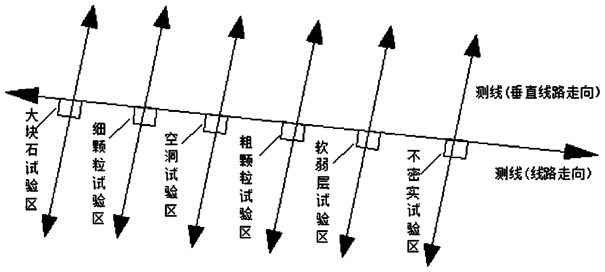
[0083] In the embankment section (k192+898~k192+948) of the second bid section of the Fuxiu Second Line, the non-destructive testing research of ground radar in the subgrade abnormal area is carried out. According to the large mileage to the small mileage, set up the large stone test area, the fine particle test area, the hollow test area, the coarse particle test area, the soft clay test area (weak interlayer) and the non-compact test area. Before the layout of the subgrade defect test area, the ground radar non-destructive inspection is carried out on the subgrade, and the subgrade is scanned by radar to collect the information under the subgrade. After the landfill of each test area was completed, the entire experimental embankment section was vibrated and compacted with a road roller, and then the quality of the subgrade filling was tested again by the geological radar method, and the underground information images of the subgrade were collected.

[0084] Throughout the ex...

Embodiment 2

[0088] Embodiment two: on the basis of embodiment one, the specific process of the forward modeling simulation is:

[0089] Step 11: Use GprMax2D software to carry out forward simulation on the layered medium model, rectangular target model, circular target model and complex model, forming a double-layer medium geometric model, a three-layer medium geometric model, a weak layer geometric model, and a rectangular cavity geometry 10 models of model, geometric model of rectangular cave, geometric model of large rock, geometric model of large rock, geometric model of multi-circular cavity, geometric model of double-layer multi-circular cavity and multi-shaped cavity model;

[0090] In the layered medium model, due to the difference in electrical parameters between layers, there is an obvious layer interface in the simulation image, and the specific layer interface can be calculated according to the propagation speed and travel time of the electromagnetic wave in the medium layer. ...

Embodiment 3

[0093] Embodiment 3: roadbed defect atlas generation roadbed defect atlas specifically includes:

[0094] The characteristics of subgrade defects corresponding to the defect map generated by the double-layer medium model simulation are: because of the uniformity of the medium, the medium interface formed by radar wave reflection is horizontal and continuous. The dark straight line at the top is the air direct wave, and the yellow straight line below the direct wave is the interface between the air and the first layer of medium. Due to the high energy and strong reflection of the radar wave, the interface is more obvious. For example: the straight line that appears around 42ns and runs through the whole picture is the dividing line between the first layer medium and the second layer medium, and the round-trip travel time of electromagnetic waves in the first layer medium is about 35ns. According to formula (ε=12), knowing that the traveling speed of the electromagnetic wave ...


PUM


Abstract

The invention relates to the technical field of railway engineering detection, and provides a railway roadbed geological radar defect map analysis method and device in allusion to problems existing inthe prior art. The railway roadbed geological radar defect map analysis method comprises the steps of forming forward modeling on geological radar electromagnetic waves, preliminarily establishing aroadbed defect map, analyzing feature laws of the simulated defect map in various types of geological radar images, and forming a railway roadbed simulated geological radar typical defect map featurelibrary; setting a typical roadbed defect test area, and performing field testing by using geological radar nondestructive testing equipment, and respectively generating profile grayscale maps or waveform maps of a compaction area and the roadbed typical defect test area correspondingly; and performing comparative analysis on the generated profile grayscale maps or waveform maps of the compactionarea and the roadbed defect test area according to the simulated geological radar typical defect map feature library, and summarizing a railway roadbed actual measurement geological radar typical defect map feature library; and performing rapid non-destructive detection and defect judgment on the actual railway roadbed according to the geological radar typical defect map feature library.

Description

technical field [0001] The invention relates to the technical field of railway engineering detection, in particular to a method-level device for analyzing radar defect maps of railway subgrade ground. Background technique [0002] 1. Traditional railway subgrade detection method. At present, there are many detection indexes for evaluating the compaction quality of railway subgrade, which are mainly divided into physical indexes and mechanical indexes. Among them, physical indicators include compaction coefficient k, porosity n, relative density Dr, etc.; mechanical indicators include foundation coefficient K30, deformation modulus Ev2, dynamic deformation modulus Evd, etc. These traditional detection methods have the following deficiencies in the following three aspects. First, it is impossible to make an overall evaluation of the quality of subgrade filling. Second, the number of random inspections is limited, and there are detection dead ends. Third, the detection is time...

Claims


Application Information

Patent Timeline
Patent Type & Authority Patents(China)
IPC IPC(8): G01V3/12G01S13/88G01S13/89
CPCG01S13/887G01S13/89G01V3/12
Inventor 邓国兵陈详彭舸刘彦许正科张健刘增旭敬国民曾洲郑学军王思威
Owner CONSTR COMPANY OF CHINA RAILWAY NO 8 ENGNEERING GRP
Why Eureka
Try Eureka