Hydraulic control valve block for automatic transmission

A technology for automatic transmissions and hydraulic control valves, applied in the direction of fluid pressure actuators, servo motor components, mechanical equipment, etc., can solve the problems of oil waste, low hydraulic system efficiency, low oil utilization rate, etc., and achieve the level of integration High, efficiency-enhancing, and response-time-reducing effects

Pending Publication Date: 2018-03-06
CHINA FIRST AUTOMOBILE
View PDF5 Cites 3 Cited by
  • Summary
  • Abstract
  • Description
  • Claims
  • Application Information

AI Technical Summary

Problems solved by technology

[0005] However, in the current oil source system, the oil utilization rate is low when the engine rotates at a high speed or two pumps work at the same time, resulting in serious waste of oil and low efficiency of the hydraulic system

Method used


Image

  • Hydraulic control valve block for automatic transmission
  • Hydraulic control valve block for automatic transmission
  • Hydraulic control valve block for automatic transmission

Examples


Embodiment Construction

[0033] In order to make the technical problems, technical solutions and advantages to be solved by the present invention clearer, the following will describe in detail with reference to the drawings and specific embodiments.

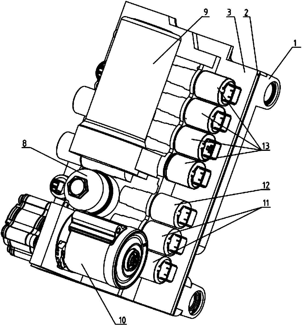
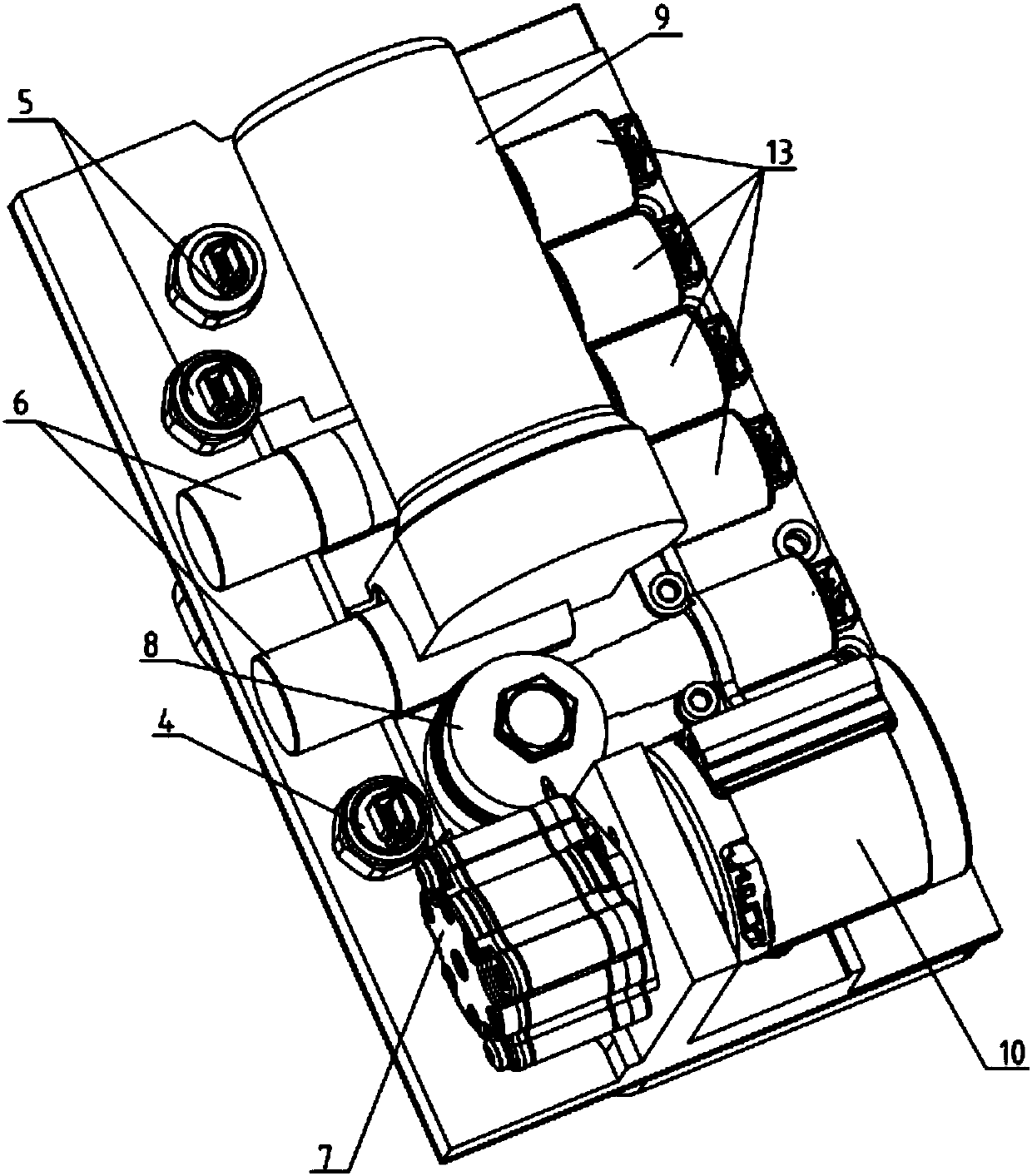
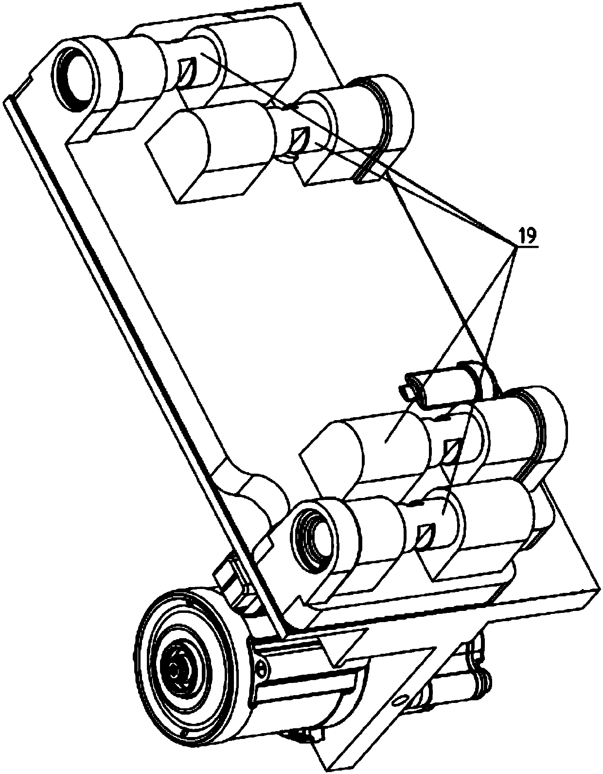
[0034] Fig. 1 (a), Fig. 1 (b), Fig. 1 (c) are the structural representations of the automatic transmission hydraulic control valve block provided by the embodiment of the present invention; figure 2 The component oil circuit diagram of the hydraulic control valve block for the automatic transmission provided by the embodiment of the present invention; Fig. 3 (a), Fig. 3 (b), and Fig. 3 (c) are the hydraulic control valve for the automatic transmission provided by the embodiment of the present invention Schematic diagram of block oil circuit.

[0035] like Figure 1(a) to Figure 3(c) As shown, the embodiment of the present invention provides a hydraulic control valve block for an automatic transmission, comprising: an upper valve plate 1, a partition pla...


PUM


Abstract

The invention provides a hydraulic control valve block for an automatic transmission. The hydraulic control valve block comprises an upper valve plate, a partition plate and a lower valve plate whichare connected in sequence through connecting pieces, wherein the upper valve plate is provided with an oil supply module, a pressure control module, a gear shifting control module and a lubricating cooling module communicating through oil channels; the oil supply module comprises a motor, an electric pump, an energy accumulator, a high-pressure filter, a high-pressure unloading valve and a one-wayvalve; the motor and the electric pump are arranged at the bottom of the upper valve plate; the energy accumulator, the high-pressure filter, the high-pressure unloading valve and the one-way valve are arranged on the upper valve plate; the pressure control module comprises a first pressure sensor and a second pressure sensor which are arranged on the upper valve plate, and a first pressure control valve and a second pressure control valve which are arranged on the right side of the upper valve plate; the gear shifting control module comprises at least one high-pressure flow control valve arranged on the upper valve plate; the lubricating cooling module comprises at least one low-pressure flow control valve arranged on the upper valve plate. According to the hydraulic control valve blockfor the automatic transmission, accurate control on the oil supply amount of the system can be realized, and waste under the high-rotating-speed condition of the engine is avoided, the flow control ismore accurate, and the system efficiency is greatly improved.

Description

technical field [0001] The invention relates to the field of automatic transmissions of hybrid vehicles, in particular to a hydraulic control valve block for automatic transmissions. Background technique [0002] With the aggravation of environmental pollution and the improvement of national automobile fuel consumption standards, there is an urgent need for an energy-saving and environment-friendly automobile drive solution. As a transitional solution between pure fuel-driven and pure electric solutions, hybrid technology has the advantages of good fuel-saving effect, relatively mature technical solutions, and strong technical scalability. [0003] In the automatic transmission of a hybrid vehicle, the core control system adopts a mechanical, electrical, and hydraulic coupling method. It mainly includes two parts: oil source system and hydraulic control system. [0004] For the oil source system, a combination of a mechanical oil pump and an electric oil pump is usually us...

Claims


Application Information

Patent Timeline
Patent Type & Authority Applications(China)
IPC IPC(8): F15B13/02F15B1/02
CPCF15B1/02F15B13/02
Inventor 姜聪慧崔江涛唐立中梁伟朋
Owner CHINA FIRST AUTOMOBILE
Why Eureka
Try Eureka