
Production line of rotating disc type loose core die composite board

A composite board and production line technology, applied in the direction of layered products, lamination devices, lamination auxiliary operations, etc., can solve the problems that the opening and closing of the mold is manual operation, unresolved, and difficulty in taking out the composite board, so as to facilitate automated production, The effect of reasonable structural design

Active Publication Date: 2018-03-09
李西安
View PDF11 Cites 2 Cited by
  • Summary
  • Abstract
  • Description
  • Claims
  • Application Information

AI Technical Summary

Problems solved by technology

[0002] The current composite panel production line generally adopts mould-based production and pressing, and there are shortcomings. The main reason is that the opening and closing of the mold is manual operation, which basically cannot be mass-produced; Cause damage; the most suitable curing time for the production of different composite panels is different, which will also affect the layout of mass production devices
The patent with the publication number CN206551166U and the patent name "Automatic Forming Mold for Heating Ceramic Tile" provides a clamshell mold. The mold can use a piston rod to open the cover, and another piston rod can be used to take out the composite board. However, because the composite board is taken out It is a top-out type, which has caused great difficulties in automatic production and placement of raw material plates. The degree of automation has not been greatly increased, and it is not easy to realize assembly line production
Existing technology does not have the solution to this

Method used


Image

  • Production line of rotating disc type loose core die composite board
  • Production line of rotating disc type loose core die composite board
  • Production line of rotating disc type loose core die composite board

Examples


Embodiment Construction

[0024] In order to clearly illustrate the technical features of this solution, the present invention will be described in detail below through specific implementation modes and in conjunction with the accompanying drawings.

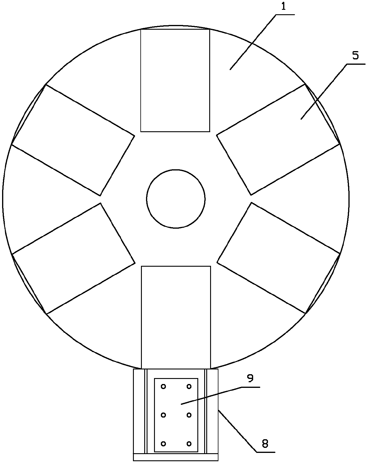
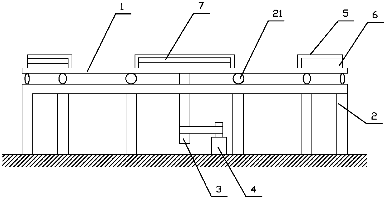
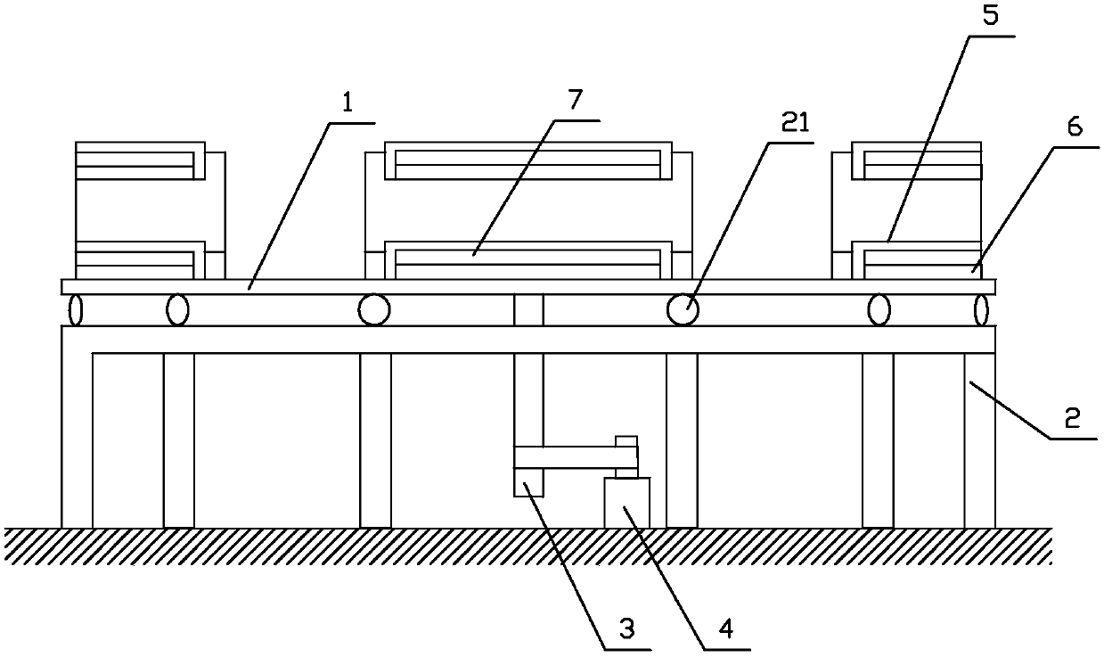
[0025] Such as Figure 1-7 As shown in the figure, a turntable-type living core mold composite board production line includes a disc 1, a number of outriggers 2 are arranged around the disc 1, and the outriggers 2 are connected to the disc 1 in movable abutment, and a rotating disc is provided under the disc 1. Power mechanism, several layers of movable core molds 5 are evenly distributed along the circumference on the upper surface of the disc 1, the end of the movable core mold 5 away from the disc 1 is provided with a mold opening 7, and a mold opening 7 is provided in the movable core mold 5 to enter and exit through the mold opening 7. The movable frame 6 of the movable core mold 5 is provided with at least one support 8 on the side of the disc 1, an...


PUM


Abstract

The invention relates to a production line of a rotating disc type loose core die composite board which comprises a disc, wherein a plurality of support legs are arranged at the periphery of the disc,the support legs are in abutting connection with the disc, a rotating power mechanism is arranged below the disc, a plurality of layers of loose core dies are uniformly distributed on the upper surface of the disc along the circumference; a die opening is formed at the end part, far away from the disc, of each loose core die; and a moving rack entering and quitting the loose core die via the dieopening is arranged in each loose core die, at least one support is arranged at the lateral part of the disc, the support is matched with the moving rack, and a rotating motor and the loose core diesare connected with a controller. The device is reasonable in structure design; an effect of respectively dealing with composite board assembly and processing and maintaining on the moving rack is achieved; since processing and maintenance need a certain turnover time, a plurality of loose core dies are arranged on the disc, the loose core dies in a processing and maintenance state and the moving rack are taken away from the support, and the active dies after processing and maintenance and the moving rack are arranged oppositely.

Description

Technical field: [0001] The invention relates to a turntable type live core mold composite plate production line. Background technique: [0002] The current composite panel production line generally adopts mould-based production and pressing, and the existing shortcomings are mainly that the opening and closing of the mold is manual operation, which basically cannot be mass-produced; after forming, it is difficult to take out the composite panel from the mold, which may cause damage Cause damage; the most suitable curing time for the production of different composite panels is different, which will also affect the layout of mass production devices. The patent with the publication number CN206551166U and the patent name "Automatic Forming Mold for Heating Ceramic Tile" provides a clamshell mold. This mold can use a piston rod to open the cover and use another piston rod to take out the composite board. It is a top-out type, which has caused great difficulties in automatic pr...

Claims


Application Information

Patent Timeline
Patent Type & Authority Applications(China)
IPC IPC(8): B32B37/12B32B37/06B32B37/00B32B38/00
CPCB32B37/0046B32B37/06B32B37/12B32B38/00
Inventor 李西安李嘉艺
Owner 李西安
Learn More