Method and apparatus to regulate oil pressure via controllable piston cooling jets

A piston cooling nozzle, oil pressure technology, used in the control of lubricant pressure, engine cooling, pump control, etc., can solve problems such as affecting flow rate, increasing component damage, and expensive variable flow oil pumps

Inactive Publication Date: 2018-03-09
FORD GLOBAL TECH LLC
View PDF5 Cites 6 Cited by
  • Summary
  • Abstract
  • Description
  • Claims
  • Application Information

AI Technical Summary

Problems solved by technology

However, not only can a variable flow oil pump be expensive, but it can inadvertently affect the flow rate of other lubrication system components such as crankshaft lubrication nozzles
Consequentl

Method used


Image

  • Method and apparatus to regulate oil pressure via controllable piston cooling jets
  • Method and apparatus to regulate oil pressure via controllable piston cooling jets
  • Method and apparatus to regulate oil pressure via controllable piston cooling jets

Examples


Embodiment Construction

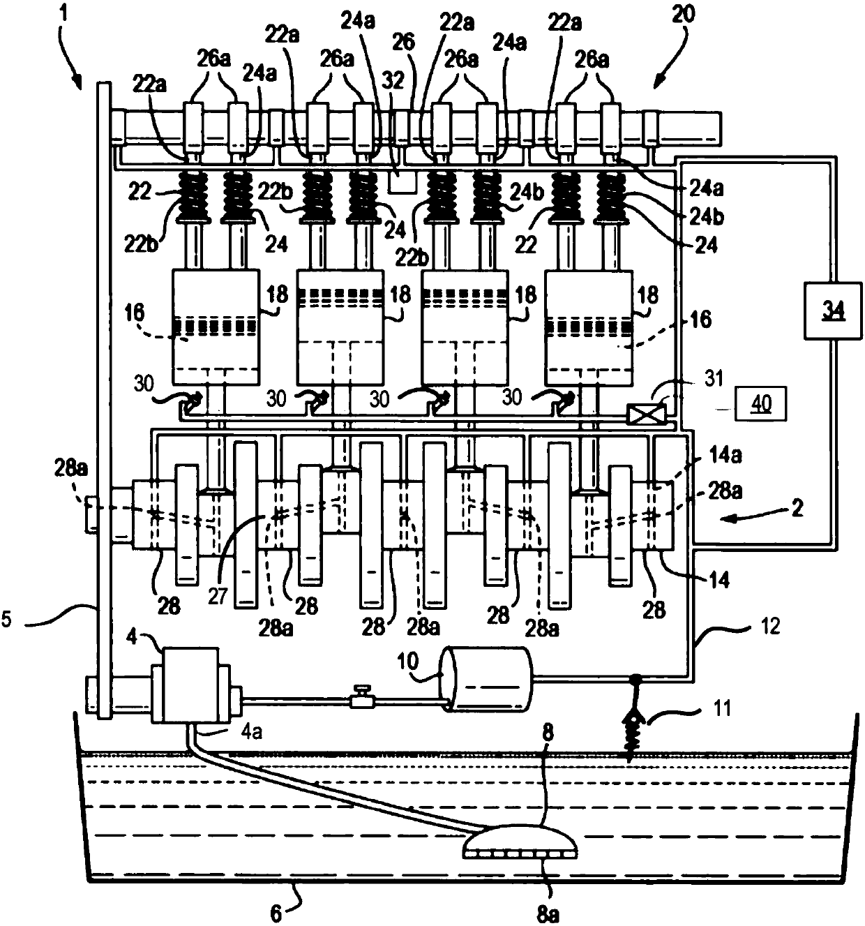
[0015] Referring to prior art FIG. 1 , a previously proposed engine assembly 1 for a motor vehicle includes an oil system 2 , a crankshaft 14 and a plurality of pistons 16 configured to reciprocate within a plurality of cylinders 18 . The engine assembly 1 further includes a valve train 20 including a plurality of intake valves 22 and exhaust valves 24 and a camshaft 26 .

[0016] Intake valve 22 and exhaust valve 24 are configured to control the flow of intake air and exhaust gas into and out of cylinder 18 , respectively. Camshaft 26 is configured to control operation of intake valve 22 and exhaust valve 24 .

[0017] The oil system 2 comprises an oil pump 4 configured to suck oil from an oil sump 6 to an inlet 4a of the oil pump via an oil pick-up 8 . The oil pump can be driven by the engine. For example, as shown in FIG. 1 , the oil pump 4 may be driven by the crankshaft 14 via the drive belt 5 . The oil pick-up 8 may include a pick-up filter 8a configured to reduce the...


PUM


Abstract

The invention relates to a method and apparatus to regulate oil pressure via controllable piston cooling jets. A method of regulating oil pressure within an engine assembly is provided. The engine assembly includes an oil pump configured to provide oil to an oil system of the engine assembly; a piston cooling jet configured to direct a jet of oil from the oil system towards a piston of an engine;and an electronic control valve configured to control the flow of oil to the piston cooling jet. The method includes operating the electronic control valve to provide a flow rate of oil above a threshold flow rate to the piston cooling jet when the engine assembly is operating above a threshold power output or engine running speed; and regulating the pressure of oil within the oil system when theengine assembly is operating below the threshold power output or engine running speed, by operating the electronic control valve.

Description

[0001] Cross References to Related Applications [0002] This application claims priority to UK Application No. 1614465.1 filed 24 August 2016. The entire contents of the above-referenced applications are hereby incorporated by reference in their entirety for all purposes. technical field [0003] The present disclosure relates to a method of regulating oil pressure within an engine assembly, and particularly, but not exclusively, to a method of regulating oil pressure while reducing frictional losses within an engine assembly. Background technique [0004] In previous engine lubrication systems, solenoid valves have been used to switch on and off cooling jets directed towards the engine pistons. However, the piston cooling solenoid cannot be gradually adjusted to further adjust the flow oil cooling nozzle at intermediate flow rates between fully open and fully closed configurations. Therefore, during certain operating conditions, there may be a mismatch between cooling no...

Claims


Application Information

Patent Timeline
IPC IPC(8): F01P3/08F01P7/14
CPCF01P3/08F01P7/14F01P2025/64F01P2025/62F01P2007/146F01M1/08F01M2250/64F16N2250/04F16N2270/20F01M1/16F01M2250/62F04C14/24F01M2250/66
Inventor A·B·戴茂斯
Owner FORD GLOBAL TECH LLC
Why Eureka
Try Eureka