Multi-row synchronous rotating injection device for assisting sintering and injection method thereof

A technology of injection device and synchronous rotation, applied in the furnace type, furnace, electrical components, etc., can solve the problems of raw material and energy waste, safety accidents, uneven sintering degree, etc.

Active Publication Date: 2018-03-13
ZHONGYE-CHANGTIAN INT ENG CO LTD
View PDF7 Cites 4 Cited by
  • Summary
  • Abstract
  • Description
  • Claims
  • Application Information

AI Technical Summary

Problems solved by technology

[0006] 1. The ejected gas cannot be uniformly mixed with the atmosphere in time: if figure 1 As shown, since there is a lower limit requirement for the injection velocity of the gas when it is injected from the injection hole through the injection tube (it must be higher than the tempering velocity), so under the existing device structure technology, the high-speed injection gas often has not yet had time to match The atmosphere in the blowing hood is evenly mixed and has already entered the material layer
This will easily lead to insufficient dilution of the gas, and in severe cases, the gas concentration entering the material layer will reach the combustion limit range, causing the gas to burn on the surface of the material layer, which will not only fail to achieve the role of auxiliary sintering, but also cause serious safety accidents;
[0007] 2. The concentration of the gas sucked into the material layer is uneven: as mentioned in point 1, when the gas enters the material layer, because there is not enough time to mix with the surrounding atmosphere, the mixing uniformity is uneven, which leads to the unevenness of the gas entering the material layer. Gas concentration is also very uneven
The gas concentration is closely related to the burning position of the gas in the sintering material layer. Once the concentration is inconsistent, the burning position of the gas in the sintering material layer is also different, which will have a serious negative impact on the sintering process and lead to low sintering efficiency.
[0008] 3. Waste of raw materials and energy: As mentioned in the previous two points, uneven gas concentration leads to uneven sintering degree, which leads to low sintering efficiency, resulting in part of the sintered material not meeting the requirements, requiring multiple sintering or directly unusable, which leads to waste of raw materials and energy

Method used


Image

  • Multi-row synchronous rotating injection device for assisting sintering and injection method thereof
  • Multi-row synchronous rotating injection device for assisting sintering and injection method thereof
  • Multi-row synchronous rotating injection device for assisting sintering and injection method thereof

Examples


Embodiment approach

[0101] According to a fourth embodiment of the present invention, there is provided a method for blowing gas using the above-mentioned blowing device 1 of the claim, comprising:

[0102] 1. Gas is fed in, and the driving device M drives the blocking pipe 61 to rotate synchronously;

[0103] 2. The gas flow rate in the gas branch pipe 4 is detected by the gas detection module, and the real-time speed of the matching plugging body 61 is judged by the speed control module according to the detected flow value, and the speed is converted into the output power of the motor, thereby changing The rotational speed of blocking pipe body 61;

[0104] 3. The sequential forward and reverse output control device presets the time point. When the time detection module detects that the running time of the driving motor reaches the preset time point, the motor control module can control the working state of the motor drive module at the preset time point. That is, forward rotation or reverse r...

Embodiment 1

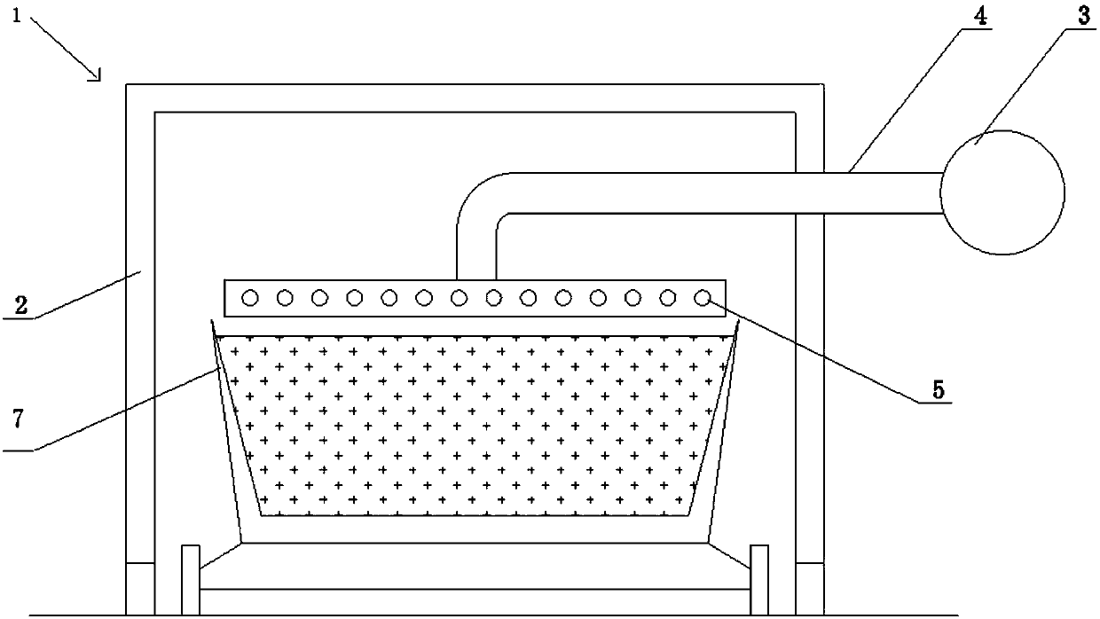
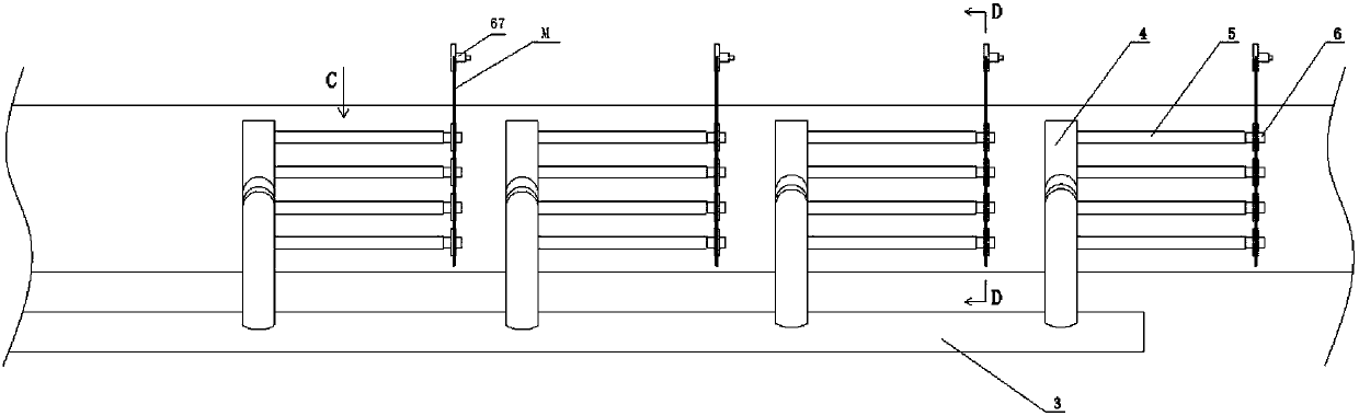
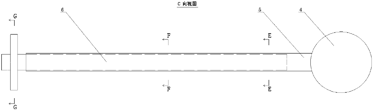
[0108] A multi-row synchronous rotary blowing device 1 for auxiliary sintering, comprising: a sintering trolley 7, an injection sealing cover 2 is arranged above the sintering trolley 7, and 20 A gas blowpipe 5, and 5 gas branch pipes 4, each gas branch pipe 4 is connected with 4 gas blowpipes 5, a gas main pipe 3 is arranged outside the injection sealing device 2, and the gas branch pipe 4 is connected through the injection sealing device 2 The gas main pipe 3 and the gas blowpipe 5, the gas blowpipe 5 comprises the blow pipe 51 and the blow hole 52 of the blow pipe, and the blow pipe 51 offers 1 group of blow holes 52 of the blow pipe along the circumferential direction, and the axial direction of the blow pipe 51 is distributed successively 10 Group blowing pipe blowing hole 52, described one group of blowing pipe blowing hole 52 is 11, and the inner coaxial line of blowing pipe 51 is provided with blocking pipe body 61, and blocking pipe body 61 one end exposes gas blowing ...

Embodiment 2

[0112] A multi-row synchronous rotary blowing device 1 for auxiliary sintering, comprising: a sintering trolley 7, an injection sealing cover 2 is arranged above the sintering trolley 7, and a 60 A gas blowpipe 5, and 10 gas branch pipes 4, each gas branch pipe 4 is connected with 6 gas blowpipes 5, a gas main pipe 3 is arranged outside the injection sealing device 2, and the gas branch pipe 4 is connected through the injection sealing device 2 The gas main pipe 3 and the gas blowpipe 5, the gas blowpipe 5 comprises the blow pipe 51 and the blow hole 52 of the blow pipe, and the blow pipe 51 offers 1 group of blow holes 52 of the blow pipe along the circumferential direction, and the axial direction of the blow pipe 51 is distributed successively 10 Group blowing pipe blowing hole 52, described one group of blowing pipe blowing hole 52 is 11, and the inner coaxial line of blowing pipe 51 is provided with blocking pipe body 61, and blocking pipe body 61 one end exposes gas blowi...


PUM


Abstract

A multi-row synchronous rotating injection device for assisting sintering includes a sintering pallet. An injection sealing cover is arranged above the sintering pallet. At least one gas blowing pipeand at least one gas branch pipe are arranged above the sintering pallet in the injection sealing cover. Each gas branch pipe is connected with at least one gas blowing pipe. A gas main pipe is arranged outside an injection sealing device. The gas branch pipe is connected with the gas main pipe and the gas blowing pipe through the injection sealing device. The gas blowing pipe includes an injection pipeline and an injection pipe blowing holes. One group of injection pipe blowing holes is formed circumferentially in the injection pipeline. At least one group of injection blowing holes is distributed in sequence in an axial direction of the injection pipeline. One group of injection pipe blowing holes has at least two injection pipe blowing holes. A plugging pipe is arranged in the injectionpipeline in the coaxial line. The plugging pipe is provided with at least one cavity opening to the injection pipe along the axis direction. The part outside the cavity is a solid or a hollow cavitysealed at both ends. The plugging pipe is connected to a driving device for driving the plugging pipe to rotate.

Description

technical field [0001] The invention relates to a multi-row synchronous rotary blowing device for auxiliary sintering and a blowing method thereof, belonging to the field of ironmaking. Background technique [0002] The sintering process is an important link in the ironmaking process. Its principle is to mix various powdery iron-containing raw materials with an appropriate amount of fuel and flux, add an appropriate amount of water, and make the materials on the sintering equipment after mixing and pelletizing. A series of physical and chemical changes occur, and finally become a sintered agglomerate product suitable for blast furnace ironmaking. [0003] For a long time, how to reduce the amount of solid fuel added in the sintering process, reduce the amount of CO2 emitted during the production process of the sintering process, and achieve the effect of energy saving and emission reduction has been a problem that people in the iron and steel technology field have been conce...

Claims


Application Information

Patent Timeline
Patent Type & Authority Applications(China)
IPC IPC(8): F27B21/08C22B1/212H02P29/00
Inventor 周浩宇孙英
Owner ZHONGYE-CHANGTIAN INT ENG CO LTD
Why Eureka
Try Eureka