
Distributed type high-frequency conversion-based modular solid-state transformer and control method therefor

A solid-state transformer, high-frequency conversion technology, used in control/regulation systems, conversion of DC power input to DC power output, instruments, etc., can solve problems such as limited application, uneven input voltage of high-frequency transformers, and difficulty in development. , to achieve the effect of improving reliability, uniform power distribution, and improving power transmission capacity

Active Publication Date: 2018-03-13
HUNAN UNIV
View PDF6 Cites 6 Cited by
  • Summary
  • Abstract
  • Description
  • Claims
  • Application Information

AI Technical Summary

Problems solved by technology

However, because this method increases the transition time of the voltage level change, it will bring a certain power loss compared with the direct use of square wave modulation.
At the same time, with the current high-frequency transformer production process, it is difficult to develop an insulation level of hundreds of kilovolts, but a high-frequency transformer with a capacity of megawatts can usually only obtain a higher insulation level by reducing the operating frequency. This limits the application of this topology in high voltage direct current (HVDC) transmission
In order to solve this problem, some scholars have proposed a structure in which multiple small-capacity high-frequency transformers are connected in series to replace a single high-frequency transformer. Uneven input voltage

Method used


Image

  • Distributed type high-frequency conversion-based modular solid-state transformer and control method therefor
  • Distributed type high-frequency conversion-based modular solid-state transformer and control method therefor
  • Distributed type high-frequency conversion-based modular solid-state transformer and control method therefor

Examples


Embodiment Construction

[0017] First, select the operation mode of the SST according to the requirements. Figure 2 is a control block diagram of a modular DC solid-state transformer based on distributed high-frequency conversion. When the SST operates in the LV voltage control mode, the HV bus voltage is fixed, and the controller adopts voltage and current dual Closed-loop control, by setting the LV voltage reference value V i2ref with the sampled voltage V i2 After doing the difference, send it to the controller. The controllers here and below can be PI, P, deadbeat, PR control and predictive control, etc., to get I i2ref , will I i2ref and I i2 After doing the difference, send it to the controller to get V hi1 and V hi2 The phase shift angle D2 between, D2 and the given D1 are jointly sent into the PWM modulation to obtain the switching signal, and the control is completed, where D1 is V hi1 and V hi2 The phase shift angle between its own high and low levels. When the SST is running in the H...


PUM


Abstract

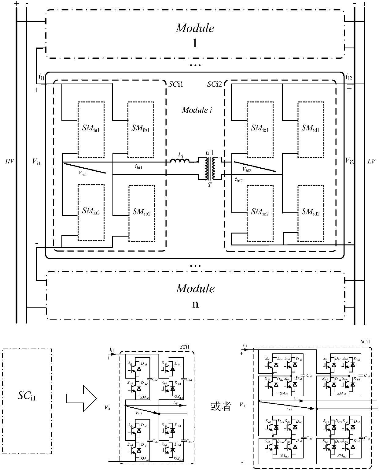
The invention discloses a distributed type high-frequency conversion-based modular solid-state transformer and a control method therefor. The modular solid-state transformer comprises multiple cascaded modules; each module comprises two sub converters SCi1 and SCi2, a high-frequency transformer and an auxiliary inductor L, wherein i represents the i module; each sub converter consists of four power sub modules; the structure of the power sub module can be a half-bridge type structure or a full-bridge type structure; each half-bridge type structure comprises a capacitor, two IGBTs and adiode in anti-parallel connection with the IGBTs; each full-bridge type structure comprises a capacitor, four IGBTs and a diode in anti-parallel connection with the IGBTs; the input end of the transformer is in a high voltage; multiple modules are connected in series to be used as the input end; the output end of the transformer is in a low voltage; and multiple modules are connected in parallel to be used as the output end. By controlling the output voltage V<hi1> of the SCi1 and the output voltage V<hi2> of the SCi2, the flowing direction of the current i<hi1> can be controlled, and equivalently, power flowing direction control is realized, and voltage conversion and isolation are completed.

Description

technical field [0001] The invention relates to a modularized solid-state transformer based on distributed high-frequency conversion, which is suitable for the application occasion of bidirectional conversion from high voltage to low voltage. Background technique [0002] Due to the vigorous development and utilization of new energy, the development of power electronics technology and the promotion of energy Internet, DC power grid technology has developed rapidly. Existing studies have shown that DC power grid technology is an effective way to solve problems such as cross-regional and large-scale power transmission and distribution, large-scale wide-area distributed new energy development and utilization, and can greatly ease the gap between large power grids and distributed energy. Contradictions, give full play to the benefits of distributed energy. The development of DC power grid has been widely concerned and recognized by experts and scholars from all over the world. ...

Claims


Application Information

Patent Timeline
Patent Type & Authority Applications(China)
IPC IPC(8): H02M3/335
CPCH02M3/3353H02M1/007
Inventor 罗安何志兴闵俊徐千鸣陈燕东易伟浪周芊帆王峰贺纤纤郭鹏黄旭程
Owner HUNAN UNIV
Learn More