
Bond head structure of 180-degree die bonder

A technology of solid crystal machine and head, which is applied in semiconductor/solid-state device manufacturing, electrical components, circuits, etc., can solve the problems of low work efficiency, processing accuracy and reliability, and achieve increased space utilization and reduced swing The effect of the arm occupying volume and improving the efficiency of die bonding

Pending Publication Date: 2018-03-16
深圳市佳思特光电设备有限公司
View PDF10 Cites 1 Cited by
  • Summary
  • Abstract
  • Description
  • Claims
  • Application Information

AI Technical Summary

Problems solved by technology

[0003] Aiming at the current problems of low working efficiency, processing accuracy and reliability of LED chip bonding, improving the structure of the bonding machine and developing a swing arm structure suitable for high-frequency and high-precision processing has become an important direction for the research and development of LED bonding machines.

Method used


Image

  • Bond head structure of 180-degree die bonder
  • Bond head structure of 180-degree die bonder
  • Bond head structure of 180-degree die bonder

Examples


Embodiment Construction

[0020] In order to further understand the features, technical means, and specific objectives and functions achieved by the present invention, the present invention will be further described in detail below in conjunction with the accompanying drawings and specific embodiments.

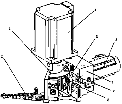
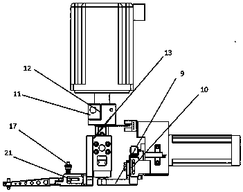
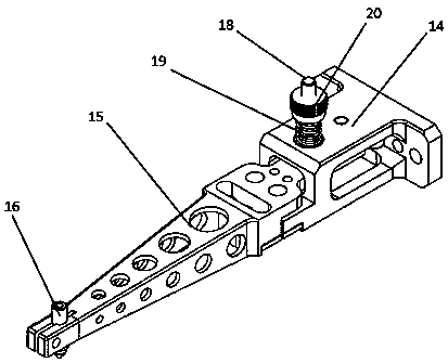
[0021] as attached figure 1 , 2 As shown in and 3, the present invention discloses a head structure of a 180 ° solid crystal machine, including a driving device and a swing arm mechanism 2, and the driving device includes a Z-axis motor 3 and a rotating motor 4, and the Z-axis motor 3 is mounted on On the Z-axis mount 7, the motor shaft of the Z-axis shaft motor 3 is equipped with an eccentric shaft 6 through a bearing 5, and a connecting rod 8 is mounted on the eccentric shaft 6, and the connecting rod 8 is equipped with a Z-axis connecting block 9, and the rotating motor 4 The motor shaft is equipped with a rotating shaft 11, and the rotating shaft 11 is provided with a swing arm guide rail 12. The ...


PUM


Abstract

A bond head structure of a 180-degree die bonder comprises a driving device and a swing arm mechanism, wherein the driving device comprises a Z-axis motor and a rotating motor; the Z-axis motor is arranged on a Z-axis installing seat; a motor shaft of the Z-axis motor is connected with an eccentric shaft through a bearing; the eccentric shaft is connected with a connecting rod; the connecting rodis connected with a Z-axis connecting block; a motor shaft of the rotating motor is connected with a rotating shaft; the rotating shaft is provided with a swing arm guide rail; the swing arm guide rail is provided with a swing arm connecting block in a clamping way; the swing arm connecting block is rotationally connected with the Z-axis connecting block through a fixed shaft and is locked througha nut; the swing arm mechanism is fixedly connected with the swing arm connecting block; the rotating motor drives the swing arm mechanism to swing within a 180-degree range. According to the bond head structure disclosed by the invention, a flexible swing arm structure is adopted, the stress of a swing arm can be regulated, and the flexibility of the swing arm can be increased; due to the designof the bond head structure of the 180-degree die bond, the die bonding speed can be increased while the layout of effectively reducing the volume of a bond head zone and optimizing all components iscarried out.

Description

technical field [0001] The invention relates to a bonding head structure used in LED crystal bonding machines, in particular to a bonding head structure capable of realizing 180° high-speed movement. Background technique [0002] At present, the domestic LED industry continues to develop, and die bonding is one of the most critical processes in the manufacture of LED devices. Therefore, the requirements for the productivity and efficiency of LED die bonding machines are getting higher and higher. The process of LED crystal solidification includes: first, apply silver glue or insulating glue on the LED bracket, and then use the swing arm device to bond the LED chip to the relevant position of the bracket through vacuum adsorption. During this process, the swing arm device needs to perform high-frequency, reciprocating, and short-distance movements. Whether the structure of the swing arm can meet the requirements of high-speed and high-precision die bonding has become an impor...

Claims


Application Information

Patent Timeline
Patent Type & Authority Applications(China)
IPC IPC(8): H01L21/67H01L33/48
CPCH01L33/48H01L21/67092H01L2933/0033
Inventor 徐大林宋宝
Owner 深圳市佳思特光电设备有限公司
Learn More