Cooling method for hot-pressing cast electronic ceramic blank

A technology of electronic ceramics and cooling method, applied in the direction of ceramic molding machine, manufacturing tools, etc., can solve the problems of affecting product quality, labor time consumption, water heat exchange speed reduction, etc., to avoid worker injury and contamination, and improve heat exchange Effect of speed, accelerated cooling rate

Inactive Publication Date: 2018-03-20
HUNAN JIAYEDA ELECTRONICS
View PDF6 Cites 1 Cited by
  • Summary
  • Abstract
  • Description
  • Claims
  • Application Information

AI Technical Summary

Problems solved by technology

However, the electronic ceramic blank formed by hot pressing is relatively soft and easy to deform; in addition, it is easy to deform due to gravity
In this way, the electronic ceramic billet that has just been hot-pressed is directly poured into the pan, and its cooling time is relatively long and the deformation is large, thereby affecting the quality of the product.
On the other hand, the hot-pressed electronic ceramic blanks are placed directly into the porcelain plate by hand, which needs to be handled gently and slowly, which greatly consumes the labor time of the workers, thereby increasing the production cost
[0009] For this reason, the Chinese patent (publication number CN103612325 A, application number 201310647210.5) discloses a cooling method for hot-pressing electronic ceramic blanks. The invention cools the electronic ceramic blanks by means of water bath cooling, but the electronic ceramic blanks fall into the water When the electronic ceramic billet is cooled, the water in the bucket does not flow, so the temperature of the water around the electronic ceramic billet is higher than that of the water far away from the electronic ceramic billet. The heat exchange rate between the ceramic blank and the surrounding water is reduced, so its cooling method needs to be improved

Method used


Image

  • Cooling method for hot-pressing cast electronic ceramic blank

Examples


Embodiment 1

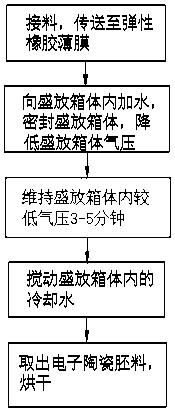
[0029] Embodiment 1, with reference to figure 1 , a method for cooling a hot-press injection electronic ceramic billet, comprising the following steps:

[0030] S1: A conveyor belt is installed under the billet outlet of the hot press injection molding machine, and a well-sealed storage box with a top cover is placed on the side of the conveyor belt away from the hot press injection molding machine;

[0031] S2: The electronic ceramic billet after hot pressing injection molding falls on the conveyor belt, and is transported to the top of the storage box by the conveyor belt. There is an elastic rubber film connected between the outer walls of the two sides of the storage box, and the electronic ceramic billet falls from the conveyor belt. on the elastic rubber membrane;

[0032] S3: Inject cooling water at 15°C into the storage box, and the liquid surface of the cooling water is immersed in the electronic ceramic blank;

[0033] S4: Cover the top cover of the storage box so ...

Embodiment 2

[0036] Embodiment 2, a cooling method for hot-press injection electronic ceramic blanks, comprising the following steps:

[0037] S1: A conveyor belt is installed under the billet outlet of the hot press injection molding machine, and a well-sealed storage box with a top cover is placed on the side of the conveyor belt away from the hot press injection molding machine;

[0038] S2: The electronic ceramic billet after hot pressing injection molding falls on the conveyor belt, and is transported to the top of the storage box by the conveyor belt. There is an elastic rubber film connected between the outer walls of the two sides of the storage box, and the electronic ceramic billet falls from the conveyor belt. on the elastic rubber membrane;

[0039] S3: Inject cooling water at 20°C into the storage box, and the liquid surface of the cooling water is immersed in the electronic ceramic blank;

[0040] S4: Cover the top cover of the storage box so that the inside of the storage b...

Embodiment 3

[0043] Embodiment 3, a method for cooling a hot-press injected electronic ceramic blank, comprising the following steps:

[0044] S1: A conveyor belt is installed under the billet outlet of the hot press injection molding machine, and a well-sealed storage box with a top cover is placed on the side of the conveyor belt away from the hot press injection molding machine;

[0045] S2: The electronic ceramic billet after hot pressing injection molding falls on the conveyor belt, and is transported to the top of the storage box by the conveyor belt. There is an elastic rubber film connected between the outer walls of the two sides of the storage box, and the electronic ceramic billet falls from the conveyor belt. on the elastic rubber membrane;

[0046] S3: Inject cooling water at 25°C into the storage box, and the liquid surface of the cooling water is immersed in the electronic ceramic blank;

[0047] S4: Cover the top cover of the storage box so that the inside of the storage box...


PUM

PropertyMeasurementUnit
Thicknessaaaaaaaaaa
Apertureaaaaaaaaaa

Abstract

The invention discloses a cooling method for a hot-pressing cast electronic ceramic blank. The cooling method comprises the following steps: arranging a conveying belt below a blank die outlet of a hot-pressing casting molding machine; putting a storage box which is good in leakproofness and provided with a top cover at one side, far away from the hot-pressing casting molding machine, of the conveying belt; making the hot-pressing cast electronic ceramic blank fall on the conveying belt and conveying the electronic ceramic blank to the upper portion of the storage box through the conveying belt; connecting an elastic rubber film between the outer walls of the two sides of the storage box; making the electronic ceramic blank fall on the elastic rubber film from the conveying belt; filling the storage box with cooling water which is at the temperature of 15 to 25 DEG C; and submerging the electronic ceramic blank into the liquid level of the cooling water. The cooling method disclosed bythe invention has the advantages of preventing the electronic ceramic blank from damages and stains caused by workers, protecting the electronic ceramic blank, accelerating evaporation and circulation of the cooling water, increasing the heat exchange speed of the electronic ceramic blank and the cooling water and shortening the cooling time of the electronic ceramic blank.

Description

technical field [0001] The invention relates to the technical field of electronic ceramic blanks, in particular to a cooling method for hot-press injection electronic ceramic blanks. Background technique [0002] Cooling refers to the process of reducing the temperature of a hot object without a phase change. There are usually three cooling methods: [0003] 1. Contact ice cooling is a common and simple cooling method, and it is also an effective cooling method. This is a method of directly contacting the item with ice to remove heat from the item. In addition to having a high cooling rate, the melting ice can keep the surface of the item moist at all times. This method is often used to cool fish, leafy vegetables and some fruits, and is also used in the processing of some foods such as luncheon meat. [0004] 2. The air cooling method is to use the cooled cold air as the cooling medium to flow through the items to absorb heat. Generally, the air temperature used when pre-...

Claims


Application Information

Patent Timeline
IPC IPC(8): B28B11/24
CPCB28B11/24
Inventor 戴承萍
Owner HUNAN JIAYEDA ELECTRONICS
Why Eureka
Try Eureka