Pipeline cable conveying method

A pipeline cable and cable transportation technology, which is applied in the direction of cable laying equipment, botanical equipment and methods, biocides, etc., can solve the problems of affecting insulation performance, slow dragging speed, and low work efficiency, so as to avoid friction damage and reduce Improvement of conveying resistance and conveying efficiency

Active Publication Date: 2018-03-20
STATE GRID CORP OF CHINA +2
View PDF8 Cites 0 Cited by
  • Summary
  • Abstract
  • Description
  • Claims
  • Application Information

AI Technical Summary

Problems solved by technology

The existing transportation method not only has slow dragging speed, low work efficiency, and often has problems such as insufficient traction force, but also causes damage to the inside of the cable to a certain extent due to strong mechanical pulling, and makes the cable drag in the pipeline, and the tube The friction between the wall and the surface layer of the cable is large, which causes the outer insulation layer of the cable to wear and seriously affects its insulation performance
[00

Method used


Image

  • Pipeline cable conveying method
  • Pipeline cable conveying method
  • Pipeline cable conveying method

Examples


Embodiment 1

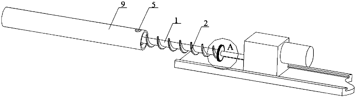
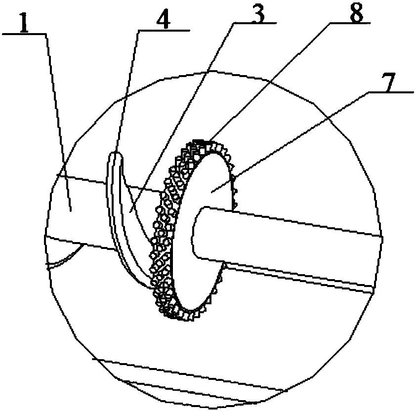
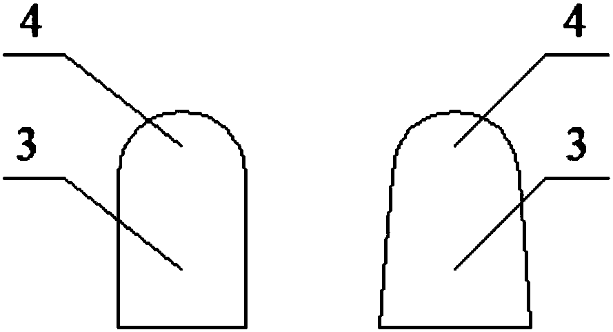
[0045] A pipeline and cable conveying method. This method is completed by means of a cable conveying device. The cable conveying device includes a horizontal drilling machine. The cable 1 is fixedly connected to the drill pipe of the horizontal drilling machine. A helical blade 2 is set and fixed on the cable 1. The spiral blade 2 includes a blade root 3 and a blade tip 4 fixedly connected to the blade root 3. The cross section of the blade tip 4 is circular, and the ratio of the thickness L of the blade root 3 to the diameter D of the blade tip 4 is 1:1. The ratio of the outer diameter of the blade 2 to the inner diameter of the pipe 9 is 0.8:1, both ends of the spiral blade 2 are discs 7, and the ratio of the diameter of the disc 7 to the inner diameter of the pipe 9 is 0.8:1, the disc The periphery of 7 is also provided with a brush ring 8, the outer diameter of the brush ring 8 is the same as the inner diameter of the pipeline 9, and the cable 1 is driven by a horizontal dr...

Embodiment 2

[0050] A pipeline and cable conveying method. This method is completed by means of a cable conveying device. The cable conveying device includes a horizontal drilling machine. The cable 1 is fixedly connected to the drill pipe of the horizontal drilling machine. A helical blade 2 is set and fixed on the cable 1. The spiral blade 2 includes a blade root 3 and a blade tip 4 fixedly connected to the blade root 3. The cross section of the blade tip 4 is circular, and the ratio of the thickness L of the blade root 3 to the diameter D of the blade tip 4 is 1:1.1. The ratio of the outer diameter of the blade 2 to the inner diameter of the pipe 9 is 0.8:1, both ends of the spiral blade 2 are discs 7, and the ratio of the diameter of the disc 7 to the inner diameter of the pipe 9 is 0.9:1, the disc The periphery of 7 is also provided with a brush ring 8, the outer diameter of the brush ring 8 is the same as the inner diameter of the pipeline 9, and the cable 1 is driven by a horizontal ...

Embodiment 3

[0055] A pipeline and cable conveying method. This method is completed by means of a cable conveying device. The cable conveying device includes a horizontal drilling machine. The cable 1 is fixedly connected to the drill pipe of the horizontal drilling machine. A helical blade 2 is set and fixed on the cable 1. The spiral blade 2 includes a blade root 3 and a blade tip 4 fixedly connected to the blade root 3. The cross section of the blade tip 4 is circular, and the ratio of the thickness L of the blade root to the diameter D of the blade tip is 1:1.2. The ratio of the outer diameter of the pipe to the inner diameter of the pipe is 0.8:1, both ends of the spiral blade 2 are discs 7, and the ratio of the diameter of the disc 7 to the inner diameter of the pipe 9 is 0.8:1, and the periphery of the disc 7 A brush ring 8 is also provided, the outer diameter of the brush ring 8 is the same as the inner diameter of the pipeline 9, and the cable 1 is driven by a horizontal drilling m...


PUM


Abstract

The invention relates to a pipeline cable conveying method, and belongs to the pipeline cable field. The pipeline cable conveying method is completed by means of a cable conveying device. The cable conveying device includes a horizontal drilling machine, wherein the cable is fixedly connected with a drilling pole of the horizontal drilling machine; spiral blades sleeve and are fixed on the cable;each spiral blade includes a blade root and a blade tip which is fixedly connected with the blade root; the cross section of the blade tip is circular; the ratio between the thickness L of the blade root and the diameter of the blade tip is 1: (1-1.2); the cable is driven by the horizontal drilling machine to form a spiral pipeline cable conveying structure, and based on the structure, the spiralblades sleeve the periphery of the cable and are fixed; the cable is fixedly connected with the drilling pole of the horizontal drilling machine; the end head of the cable is arranged in the end headof the pipeline; the horizontal drilling machine is started, and the blocking particles are injected into from a feed opening above the end head of the pipeline; and during the process that the cableis conveyed to the other end head of the pipeline, the blocking particles are filled in the pipeline; and then the horizontal drilling machine is closed, and the end head, with the feed opening, of the pipeline is cut off, and then the process is completed. The pipeline cable conveying method can easily, quickly and completely convey the cable and the blocking particles to be in place synchronously.

Description

technical field [0001] The invention belongs to the technical field of pipeline cables and relates to a method for conveying pipeline cables. Background technique [0002] Due to the thick diameter and heavy weight of the pipeline cable, it is very difficult to operate the cable when it is inserted into the pipeline during the laying project of the pipeline cable. At present, the transportation of pipeline cables usually uses a large amount of manpower and large-scale mechanical traction such as winches, tractors, and tractors. The existing transportation method not only has slow dragging speed, low work efficiency, and often has problems such as insufficient traction force, but also causes damage to the inside of the cable to a certain extent due to strong mechanical pulling, and makes the cable drag in the pipeline, and the tube The friction between the wall and the surface layer of the cable is relatively large, which causes the outer insulation layer of the cable to wea...

Claims


Application Information

Patent Timeline
IPC IPC(8): H02G1/08A01N65/42A01P17/00C08L23/16C08L91/00C08K13/02C08K3/22C08K5/09C08K5/40
Inventor 李燕孟丽环王力邓亮潘旭史运涛张业李朝辉
Owner STATE GRID CORP OF CHINA
Why Eureka
Try Eureka