Separately controlled multichannel carving and milling machine

A separate control and engraving machine technology, applied in the direction of manufacturing tools, metal processing machinery parts, large fixed members, etc., can solve the problems of low product yield, large area required for equipment placement, and low processing accuracy

Pending Publication Date: 2018-03-23
东莞市德夫曼科技实业有限公司
View PDF13 Cites 3 Cited by
  • Summary
  • Abstract
  • Description
  • Claims
  • Application Information

AI Technical Summary

Problems solved by technology

[0002] The CNC engraving machine or engraving and milling machine currently used in electronic products, such as the patent number "201721293580.3" previously applied by the applicant, and the patent name is "a new type of tool magazine structure", all the tool magazine spindles are controlled by a single It is controlled by the control system, and all tool magazine spindles share one worktable, which leads to the following disadvantages: 1. One machine can only process the same product at the same time. Since the X-axis and Y-axis share the same worktable, As a result, each tool magazine spindle can only process the product with the same program; 2. Since the X-axis and Y-axis share the same work platform, and there is a tool error between two adjacent tool magazine spindles, when it needs to At the same time, there is no way to separately perform tool compensation for the tool holder on a certain spindle during processing, so that the processing accuracy is low, so that the size of the processed product cannot meet the uniform standard. The yield rate is low; 3. In order to ensure that the processing size of high-precision and high-demand products reaches a uniform standard, companies usually only use one spindle to operate, and the remaining spindles of the tool magazine do not operate. The production efficiency is low, and the remaining spindles are wasted due to idleness; 4. In order to process products with high processing precision requirements, each machine can only use a single spindle for processing, so for mass production Enterprises must purchase multiple machines, which leads to high purchase costs and large area required for equipment placement; 5. In order to solve the problem that multiple spindles and multiple stations of one machine can process products at the same time, The enterprise must equip each machine with more than one worker to change the tool between two different processing procedures. The worker needs to stop the machine to operate when changing the tool. This method not only makes the labor intensity and labor cost high for the worker, but also leads to The production cycle of the product is long and the production efficiency is low

Method used


Image

  • Separately controlled multichannel carving and milling machine
  • Separately controlled multichannel carving and milling machine
  • Separately controlled multichannel carving and milling machine

Examples


Embodiment Construction

[0026] In order to facilitate the understanding of the present invention, the present invention will be described more fully below with reference to the associated drawings. Preferred embodiments of the invention are shown in the accompanying drawings. However, the present invention can be embodied in many different forms and is not limited to the embodiments described herein. On the contrary, the purpose of providing these embodiments is to make the disclosure of the present invention more thorough and comprehensive.

[0027]Unless otherwise defined, all technical and scientific terms used herein have the same meaning as commonly understood by one of ordinary skill in the technical field of the invention. The terminology used herein in the description of the present invention is only for the purpose of describing specific embodiments, and is not intended to limit the present invention.

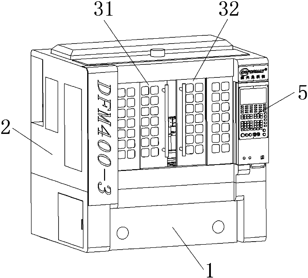
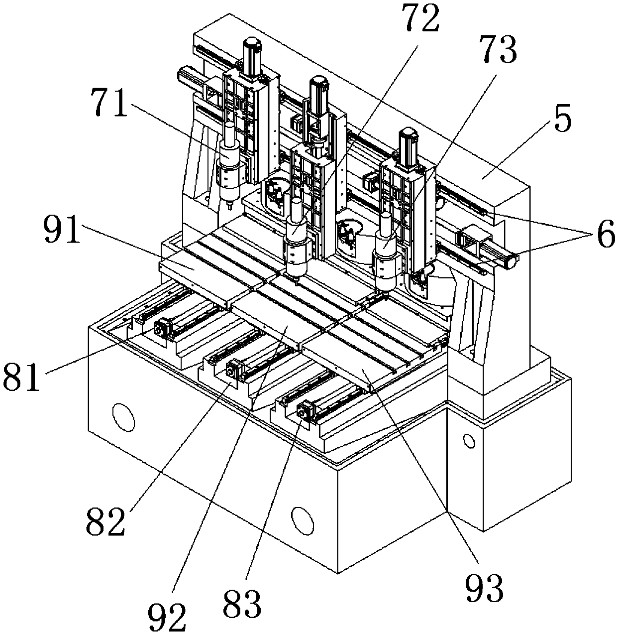
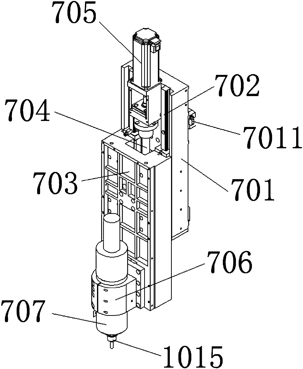
[0028] In this example, refer to Figure 1 to Figure 6 As shown, a multi-channel indiv...


PUM


Abstract

The invention relates to a separately controlled multichannel carving and milling machine. The separately controlled multichannel carving and milling machine comprises a machine tool, a case, a left sliding door, a right sliding door, a control panel, a CNC (Computer Numerical Control) control system, a portal cross beam, a linear guide rail, a plurality of X-axis sliding plate mechanisms, a plurality of Z-axis sliding plate mechanisms, a plurality of Y-axis mechanisms, a plurality of workbenches and a plurality of tool changer disks. According to the separately controlled multichannel carvingand milling machine, main shafts and the workbenches can be separately controlled respectively, so that products can be synchronously or asynchronously processed by the main shafts, the products canalso be separately processed by the main shafts in multichannel different procedures, and the universality is good; the machining error of each shank cutter can be separately adjusted through the CNCcontrol system, so that the size of the produced products reaches the uniform standard, and the rate of good products is high; and the shank cutters of different specifications can be automatically replaced by the main shafts through the adjustment of the Y-axis mechanisms, so that the labor intensity of workers and the labor cost are reduced, the production cycle of the products is shortened, andthe production efficiency is high.

Description

technical field [0001] The invention relates to a multi-channel individually controlled fine carving machine. Background technique [0002] The CNC engraving machine or engraving and milling machine currently used in electronic products, such as the patent number "201721293580.3" previously applied by the applicant, and the patent name is "a new type of tool magazine structure", all the tool magazine spindles are controlled by a single It is controlled by the control system, and all tool magazine spindles share one worktable, which leads to the following disadvantages: 1. One machine can only process the same product at the same time. Since the X-axis and Y-axis share the same worktable, As a result, each tool magazine spindle can only process the product with the same program; 2. Since the X-axis and Y-axis share the same work platform, and there is a tool error between two adjacent tool magazine spindles, when it needs to At the same time, there is no way to separately pe...

Claims


Application Information

Patent Timeline
Patent Type & Authority Applications(China)
IPC IPC(8): B23Q41/04B23Q1/00
CPCB23Q1/0009B23Q41/04
Inventor 陈科张乐
Owner 东莞市德夫曼科技实业有限公司
Why Eureka
Try Eureka