
Pyrolysis gasification furnace

A pyrolysis gasification and furnace body technology, applied in incinerators, lighting and heating equipment, combustion methods, etc., can solve problems such as energy consumption, land waste, and environmental pollution, and achieve improved combustion effects, increased safety, and improved The effect of combustion efficiency

Pending Publication Date: 2018-03-23
河北涞然环保科技有限公司
View PDF0 Cites 0 Cited by
  • Summary
  • Abstract
  • Description
  • Claims
  • Application Information

AI Technical Summary

Problems solved by technology

[0002] The current garbage and sludge treatment methods in my country mostly use three methods: sanitary landfill, composting and incineration. These three existing methods have the disadvantages of polluting the environment, wasting land and consuming a lot of energy. Therefore, the development of new garbage and sludge Sludge treatment methods and processes are imperative

Method used


Image

  • Pyrolysis gasification furnace
  • Pyrolysis gasification furnace
  • Pyrolysis gasification furnace

Examples


Embodiment Construction

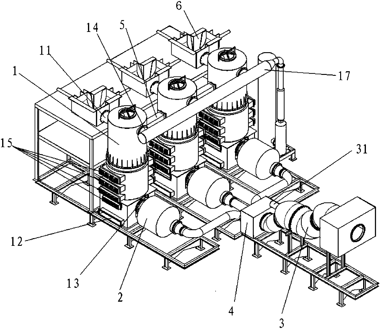
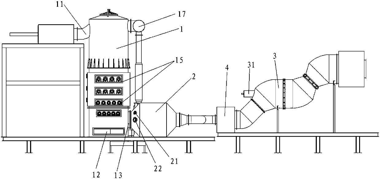
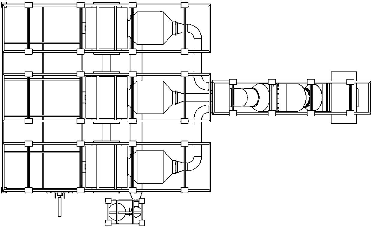
[0030] Refer to attached Figures 1 to 4 As shown, the pyrolysis gasification furnace of the present invention includes a furnace body 1 , a combustion chamber 2 and a rapid cooling tube 3 .

[0031] The furnace body 1 is a sealable chamber with a feed inlet 11 on its upper part, a slag discharge port 12 and an exhaust port 13 on its lower part, and an air inlet for feeding auxiliary gas on the side wall of the furnace body 1. . The feeding port 11 is connected with the hydraulic closed continuous feeding system 6 . This body of heater 1 inside is provided with four-layer fire grate 15, then this fire grate 15 is divided into four combustion chambers by body of heater 15, and the body of heater side wall of each combustion chamber is all provided with air inlet, and organic waste is discharged from the upper part. The feed port 11 enters the uppermost combustion chamber after being sealed and fed through the hydraulic closed continuous feeding system 6, where the organic mat...


PUM


Abstract

The invention discloses a pyrolysis gasification furnace which comprises a furnace body, a combustion chamber and a rapid cooling pipe. The furnace body is an airtight cavity body, a feeding port is formed in the upper portion of the furnace body, a slag outlet and an exhaust opening are formed in the lower portion of the furnace body, and an air inlet is formed in the side wall of the furnace body. Four layers of fire grates are arranged in the furnace body, and grate bars on the fire grates are arranged in a rotating manner, and the distance of the grate bars of the lower layer of fire grateis equal to or smaller than the distance of the grate bars of the upper layer of fire grate. An inlet of the combustion chamber is connected with the exhaust opening of the furnace body, and an ignition device is arranged on the side wall of the position of the inlet of the combustion chamber. An outlet of the combustion chamber is connected with an inlet of the rapid cooling pipe. At least one air distribution pipe is arranged on the rapid cooling pipe. By means of the pyrolysis gasification furnace, due to the fact that the airtight furnace body with the four layers of fire grates is arranged, organic garbage can be sufficiently combusted, the furnace temperature can reach 1200 DEG C and is higher than that of a fluidized bed furnace and a grate furnace, the temperature interval of 360DEG C to 820 DEG C generating dioxin is avoided, in addition, the rapid cooling principle is adopted so that high-temperature gas can be rapidly cooled to the temperature below 200 DEG C, dioxin reduction is controlled, and the discharging index of the gasification furnace is far superior to the national standard.

Description

technical field [0001] The invention relates to the technical field of waste incineration treatment, in particular to a pyrolysis gasifier. Background technique [0002] The current garbage and sludge treatment methods in my country mostly use three methods: sanitary landfill, composting and incineration. These three existing methods have the disadvantages of polluting the environment, wasting land and consuming a lot of energy. Therefore, the development of new garbage and sludge Sludge treatment methods and processes are imperative. How to reduce the discharge of garbage and sludge, realize the harmlessness, reduction, and recycling of garbage and sludge, turn garbage and sludge into treasure, and realize the resource recycling of urban solid waste is a key issue in my country. An important topic in modern urban management. [0003] On the basis of the above background, the present invention creates a new pyrolysis gasifier, which can effectively reduce the emission of dio...

Claims


Application Information

Patent Timeline
Patent Type & Authority Applications(China)
IPC IPC(8): F23G5/00F23G5/027F23G5/44
CPCF23G5/002F23G5/006F23G5/0276F23G5/44F23G2209/12F23G2209/20F23G2201/303F23G2201/302F23G2203/105
Inventor 石宏陶晓东李天庆高明超李中华
Owner 河北涞然环保科技有限公司
Learn More