FPGA and OTN based data acquisition and transmission system
A transmission system and data acquisition technology, applied in transmission systems, electromagnetic wave transmission systems, optical fiber transmission, etc., can solve problems that cannot be solved by FPGA and reduce data transmission rate, achieve low maintenance cost, increase data transmission rate, and improve communication quality Effect
- Summary
- Abstract
- Description
- Claims
- Application Information
AI Technical Summary
Problems solved by technology
Method used
Image
Examples
Embodiment 1
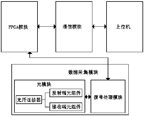
[0032] combined with figure 1As shown, a data acquisition and transmission system based on FPGA and OTN includes a data acquisition module for collecting optical signals and performing photoelectric conversion, the data acquisition module is connected with an FPGA module, and the FPGA module is connected to the communication module and The upper computer, the data acquisition module includes an optical module and a signal processing module, the optical module includes an optical fiber connector connected to an optical fiber, the optical fiber connector is connected to a transmitting end optical component and a receiving end optical component, and the optical module It also includes a control circuit connected to the optical component at the transmitting end and the optical component at the receiving end. The control circuit includes an automatic temperature control unit for controlling the temperature of the optical component at the transmitting end and an output control unit f...
Embodiment 2
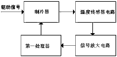
[0036] On the basis of Example 1, in conjunction with the attached Figure 1-2 As shown, the automatic temperature control unit includes a temperature sensor circuit for detecting the temperature of the optical component at the transmitting end, the temperature sensor circuit is connected to a signal amplification circuit, the output end of the signal amplification circuit is connected to the first processor, The first processor is driven and connected to a refrigerator.
[0037] working principle:
[0038] The temperature sensor circuit in the automatic temperature control unit is used to detect the temperature of the optical component at the transmitting end. The temperature sensor uses a thermistor, and the temperature change of the optical component at the transmitting end is reflected by the change of the resistance of the thermistor. The change of the current in the temperature sensor circuit causes a change in the magnitude of the current. Therefore, according to the c...
Embodiment 3
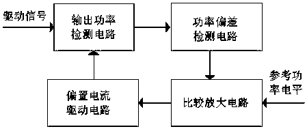
[0040] On the basis of embodiment 2, in conjunction with the attached Figure 1-3 As shown, the automatic power control unit includes an output power detection circuit for detecting the optical power of the optical component at the transmitting end, the output power detection circuit is connected with a power deviation detection circuit, and the power deviation circuit is connected with a comparison amplifier circuit , the comparison amplifier circuit is connected with a bias current drive circuit for controlling the bias current tracking current threshold of the optical component at the transmitting end, and the bias current drive circuit is connected with the output power detection circuit.
[0041] working principle:
[0042] The automatic power control unit includes an output power detection circuit, which is used to detect the output power of the optical component at the transmitting end. Usually, a photodetector packaged in an optical module is used for backlight detecti...
PUM
 Abstract
Description
Claims
Application Information
 - R&D
- Intellectual Property
- Life Sciences
- Materials
- Tech Scout
- Unparalleled Data Quality
- Higher Quality Content
- 60% Fewer Hallucinations
Browse by: Latest US Patents, China's latest patents, Technical Efficacy Thesaurus, Application Domain, Technology Topic, Popular Technical Reports.
© 2025 PatSnap. All rights reserved.Legal|Privacy policy|Modern Slavery Act Transparency Statement|Sitemap|About US| Contact US: help@patsnap.com


