Robot milling double-shaft compound cutter device and method

A compound tool and robot technology, applied in the direction of milling machines, milling machine equipment, manufacturing tools, etc., can solve the problems of step effect, size error, increased cost, etc., and achieve the effect of fewer components, convenient speed adjustment, and easy installation

Active Publication Date: 2018-03-30
BEIJING UNIV OF TECH
View PDF7 Cites 9 Cited by
  • Summary
  • Abstract
  • Description
  • Claims
  • Application Information

AI Technical Summary

Problems solved by technology

It can be seen that the control of the forming shape is the main bottleneck of the additive manufacturing technology of metal parts. This is because the STL format and two-dimensional layering technology are used in the discretization process of itself, resulting in dimensional errors and step effects.
Generally speaking, the smaller the layer thickness, the higher the accuracy, but the longer it takes, which increases the cost

Method used


Image

  • Robot milling double-shaft compound cutter device and method
  • Robot milling double-shaft compound cutter device and method
  • Robot milling double-shaft compound cutter device and method

Examples


Embodiment Construction

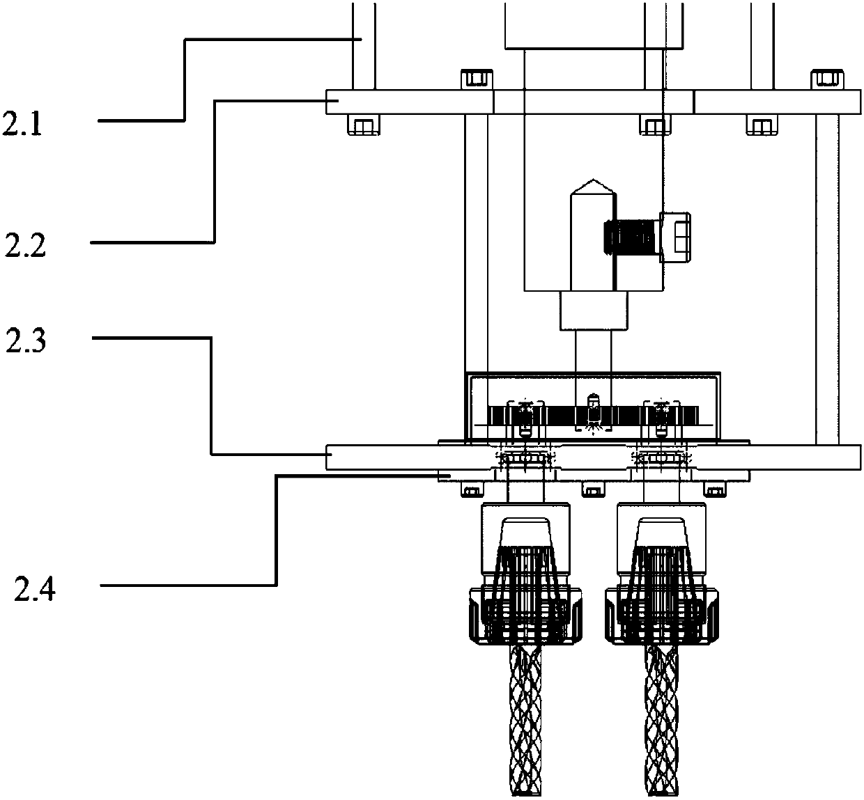
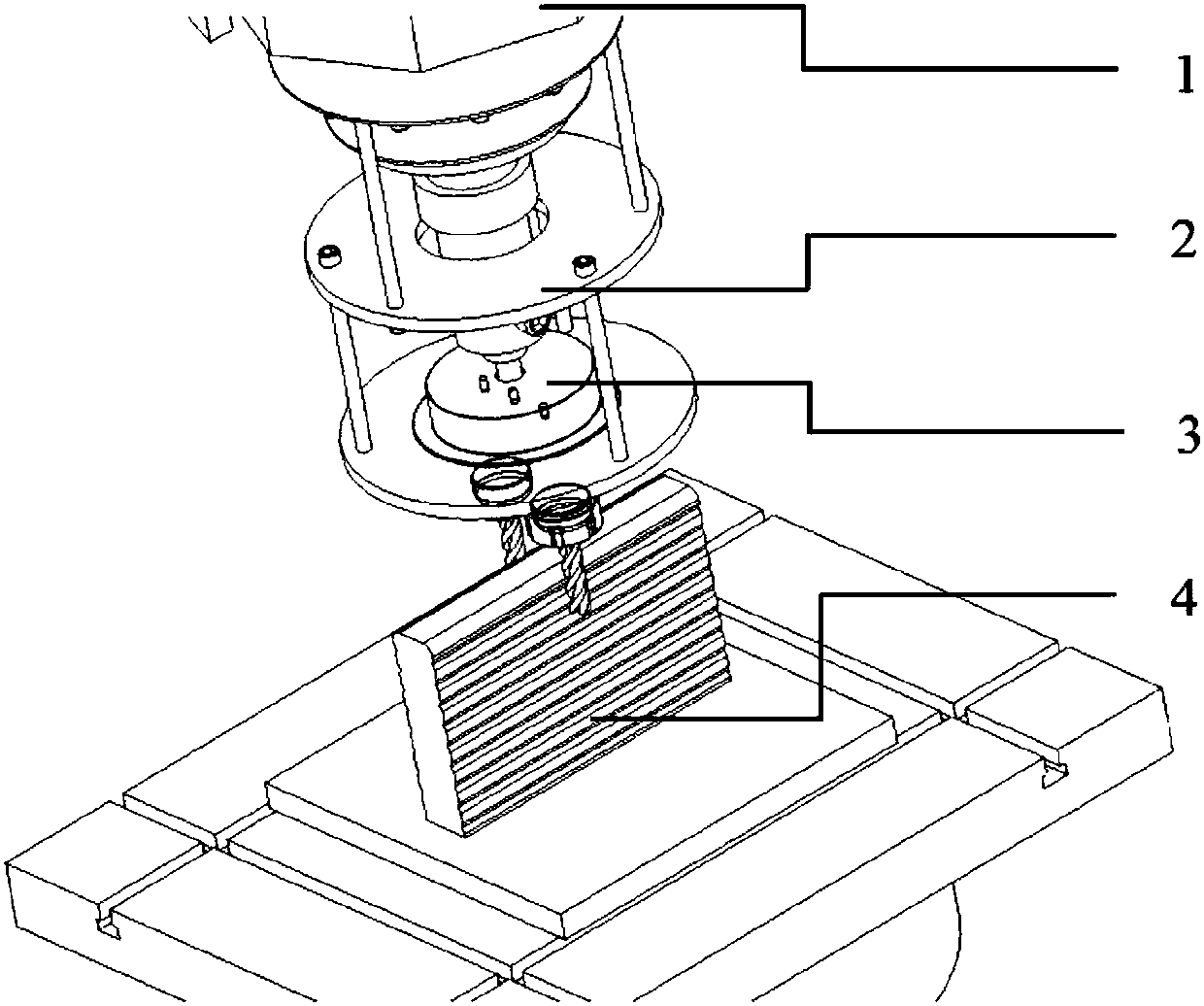
[0035] In this example, figure 1 It is a schematic diagram of the structure of the milling compound tool device. Such as figure 1 As shown, the robot milling two-axis compound tool device is composed of a robot drive unit, a connecting bracket, a compound tool device and a workpiece to be processed. Wherein, the connecting bracket is composed of bolts, an upper cover plate, a supporting plate and a lower cover plate.

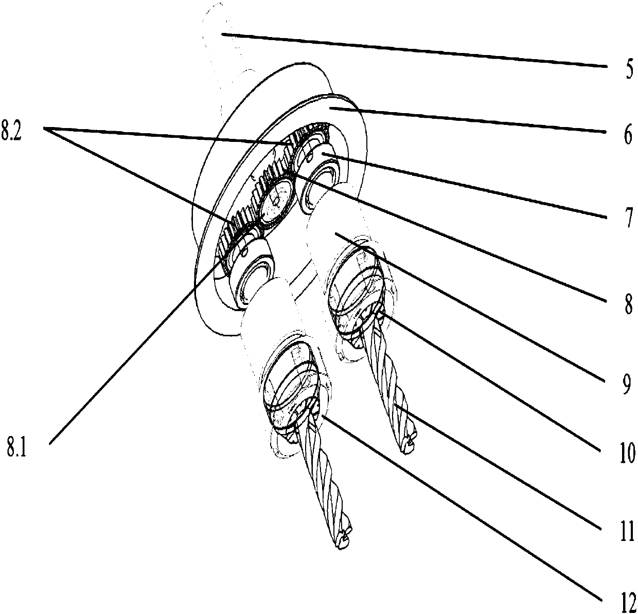
[0036] The composite cutter device is connected to the robot drive unit through the connecting bracket, and the robot drive unit drives the dual-axis cutter system of the composite cutter device to rotate, thereby realizing double-sided simultaneous cutting on the side of the thin-walled wall. The rotation speed and rotation direction of the tool can be adjusted through the robot drive unit and the robot control system. The connecting bracket supports the compound cutter device, and the whole device is connected and fixed to the flange plate of the end joint ...


PUM


Abstract

The invention relates to a robot milling double-shaft compound cutter device and a method, and belongs to the field of cold and hot compound working in machining. The device consists of a robot driving unit, a connecting bracket, a compound cutter device and a machined workpiece. The compound cutter device comprises a robot connecting shaft, an upper cover, a bearing, a gear set, a shank, a springchuck, milling cutters and a shank cap. The robot driving unit drives the milling cutters in the compound cutter device to rotate to machine the machined workpiece. The robot driving unit is fixedlyconnected with the robot connecting shaft of the compound cutter device to drive a driving gear. The driving gear drives two driven gears to oppositely rotate, so that the two milling cutters are driven to oppositely rotate to realize synchronous milling of double shafts by double side surfaces of the machined workpiece. The device is simple in structure, convenient to install and lower in cost, and replaces the milling cutters to change the side surface sizes of the machined workpiece, namely the thickness of a wall, so as to achieve the machining precision and the surface quality requirements.

Description

technical field [0001] The invention relates to a structure and method of a composite cutting tool for reducing material and milling by a robot, which belongs to the field of combined cold and hot processing in mechanical processing, and is tooling equipment for milling and cutting material leveling in the integrated composite manufacturing of adding and subtracting materials, as well as installation and use methods. Background technique [0002] In recent years, under the background of resource saving and high-efficiency manufacturing, the additive manufacturing technology based on the "additive" processing mode has shown broad application prospects in the manufacture of thin-walled parts with complex shapes. Additive manufacturing technology is a technology that uses CAD design data to manufacture solid parts by accumulating materials layer by layer. Additive manufacturing technology represents the development trend of production mode and advanced manufacturing technology....

Claims


Application Information

Patent Timeline
Patent Type & Authority Applications(China)
IPC IPC(8): B23C1/08B23C3/00B23C9/00
CPCB23C1/08B23C3/00B23C9/005
Inventor 田宏宇陈树君李方肖珺余旭石俊彪
Owner BEIJING UNIV OF TECH
Why Eureka
Try Eureka