Shaping chain tooth with amplified and changed tooth body, and sliding wedge and zipper matched with shaping chain tooth

A technology of sprocket teeth and tooth body, applied in the field of sliding wedge, can solve the problems of reduced meshing function, undisclosed, deformation, etc., and achieve the effects of preventing strain, strengthening structural strength, and being easy to disengage.

Inactive Publication Date: 2018-04-03
曹昌文
View PDF13 Cites 3 Cited by
  • Summary
  • Abstract
  • Description
  • Claims
  • Application Information

AI Technical Summary

Problems solved by technology

However, changing the shape of the upper half of the meshing part in the previous proposal will definitely reduce its meshing function. Therefore, in the previous proposal, it is unfavorable and inappropriate to change the shape of the upper half of the meshing part in order to highlight the appearance shape of the chain teeth or make the touch feel better. of
Furthermore, the above-mentioned document does not disclose the following features, that is, the shape of the upper half of the zipper tooth body is enlarged and patterned, and the volume length and width of the upper and lower halves of the tooth body should preferably be t

Method used


Image

  • Shaping chain tooth with amplified and changed tooth body, and sliding wedge and zipper matched with shaping chain tooth
  • Shaping chain tooth with amplified and changed tooth body, and sliding wedge and zipper matched with shaping chain tooth
  • Shaping chain tooth with amplified and changed tooth body, and sliding wedge and zipper matched with shaping chain tooth

Examples


Example Embodiment

[0043] The following detailed description based on the embodiment shown in the figure is as follows:

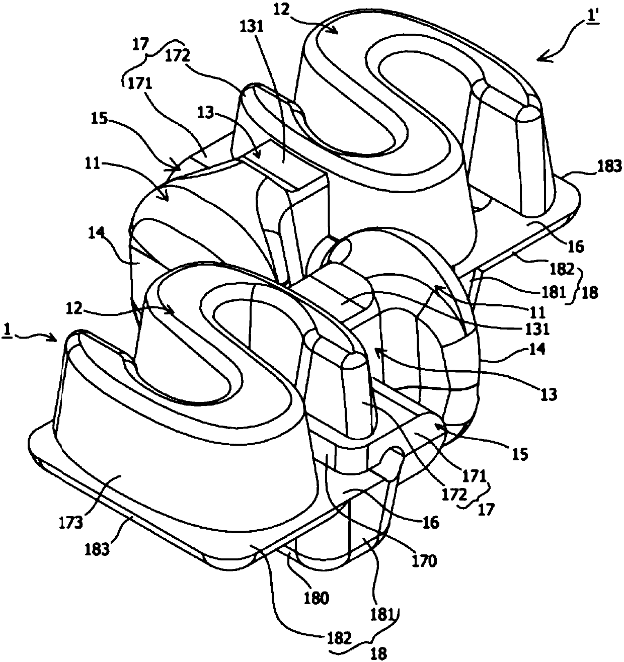
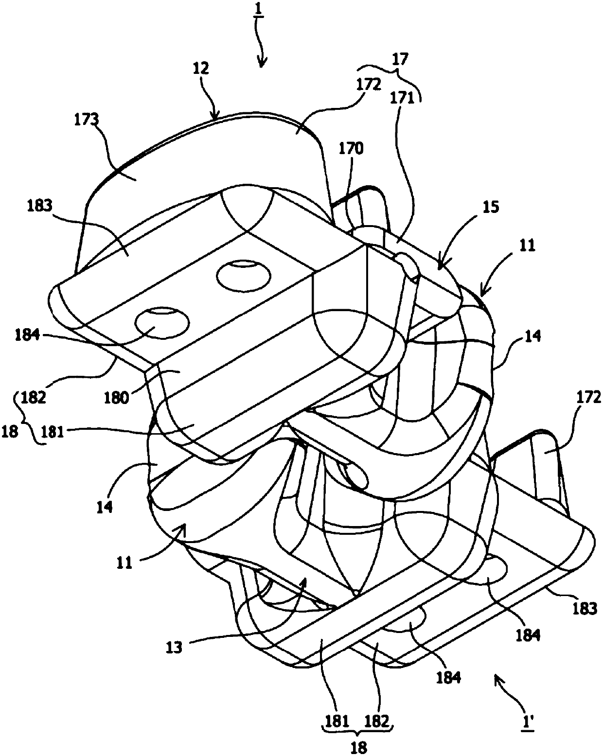
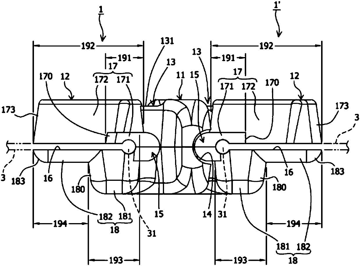
[0044] Such as Figure 1 to Figure 2 As shown in the figure, a pair of shaped sprocket 1, 1'is revealed, and they are alternately opposite to each other. The structure and shape of the two shaped sprocket 1, 1'are the same. One end is the meshing part 11, and the other One end is the tooth body portion 12 corresponding to the engagement portion 11. A narrow neck portion 13 is formed between the engagement portion 11 and the tooth body portion 12, and the outer top edge of the engagement portion 11 has a concave groove 14 , And on the left and right sides of the connection between the body portion 12 and the neck portion 13, there are shoulder portions 15 with block-like protrusions. The shoulder portions 15 can be inserted into the meshing grooves of the alternately opposed forming sprocket 1'or 1 14 to achieve a fitting function, and the tooth body portion 12 has a notch toward...


PUM


Abstract

The invention provides a shaping chain tooth being more striking through tooth body size amplification and shape change, a sliding wedge matched with the shaping chain tooth, and a zipper with the shaping chain tooth and the sliding wedge. The shaping chain tooth is a chain tooth formed through metal casting or plastic injection molding; after the amplification on an upper clamping part and a lower clamping part of the tooth body part, the size and the area are greater than those of a conventional tooth body; the longitudinal length of the upper clamping part can be greater than or equal to the longitudinal length of the lower clamping part; the shape of the upper clamping part is characters, numbers or signs and the like; visual effects different from the conventional tooth body can be generated; no flange part is formed at the two sides of an upper wing plate of the sliding wedge; flange parts are only arranged at the two sides of a lower wing plate, so that a greater slot seam is formed between the upper wing plate and the lower wing plate; support parts of the upper clamping part and the lower clamping part of the chain tooth and weaving belts can jointly pass through the slotseam; good interaction relationship is generated; and after the zipper and double weaving belts are combined with the double-row shaping chain tooth and the sliding wedge, an unsealed or sealed component with good recognition performance and advertisement benefits is realized.

Description

technical field [0001] The invention relates to a zipper, especially a plurality of formed chain teeth arranged on the inner edges of two opposite webbing belts and injected by metal casting or synthetic resin, and a sliding wedge matched with the formed chain teeth. Background technique [0002] Metal zippers have been used in a wide range of fields. The traditional metal zipper manufacturing process is to pass copper strips, aluminum strips or other alloy strips through special machines, and press and fix the chain teeth on the webbing through a stamping process. And there are many defects in the sprockets fixed on the webbing, so some operators manufacture the sprockets by casting, and plate nickel or chrome on the surface to solve the problems of aesthetics, durability, better touch, and reduce manufacturing costs. , And adapt to the requirements of commercial mass production. [0003] The above sprockets formed by casting are zinc alloy sprockets, but the structure and...

Claims


Application Information

Patent Timeline
IPC IPC(8): A44B19/24A44B19/26A44B19/02
CPCA44B19/02A44B19/24A44B19/26
Inventor 曹昌文
Owner 曹昌文
Why Eureka
Try Eureka