Magnetic attraction type foreign matter removing device

A foreign body removal and magnetic suction technology, applied in the coating and other directions, can solve the problems of shortening the maintenance cycle of the laminating machine, affecting the quality of the finished product, frequent shutdown and maintenance, etc., to improve the risk of foreign bodies, easy and reliable use, and ensure product quality. Effect

Pending Publication Date: 2018-04-03
HUANGSHAN NOVEL
View PDF3 Cites 0 Cited by
  • Summary
  • Abstract
  • Description
  • Claims
  • Application Information

AI Technical Summary

Problems solved by technology

In actual production, people found that the above-mentioned laminating machine often has the problem of metal foreign matter when extruding and laminating; through the search and analysis of the cause, it was found that the material feeding pipeline of the laminating machine did not have a filter device, resulting in plastic particles at the hopper The metal foreign matter trapped in the film will directly enter the screw through the melting channel of the screw extrusion structure, and then be extruded from the die lip of the coating head
The above-mentioned metal foreign matter, on the one hand, adheres to the surface of the flexible substrate after being stretched together with the molten plastic, resulting in quality defects such as bumps in the formed composite film, which seriously affects the quality of the finished product
On the other hand, metal particles entering the screw will also damage the screw, which shortens the maintenance cycle of the laminating machine sharply, and has to be shut down frequently for maintenance, resulting in immeasurable economic losses

Method used


Image

  • Magnetic attraction type foreign matter removing device
  • Magnetic attraction type foreign matter removing device
  • Magnetic attraction type foreign matter removing device

Examples


Embodiment Construction

[0025] For ease of understanding, the specific structure and working method of the present invention are described as follows in conjunction with the accompanying drawings:

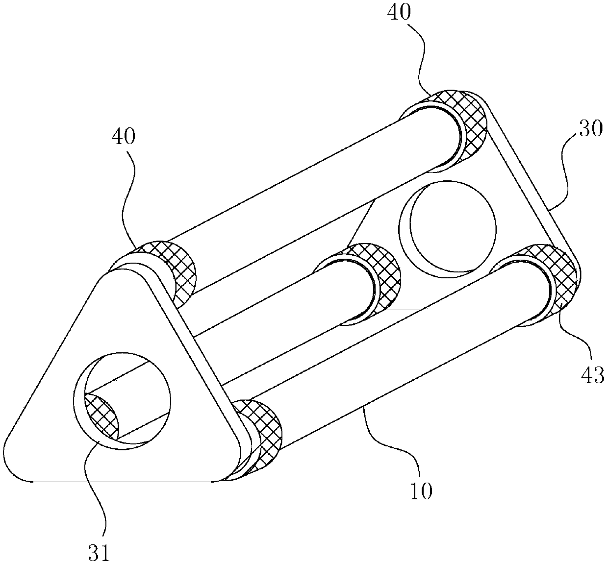
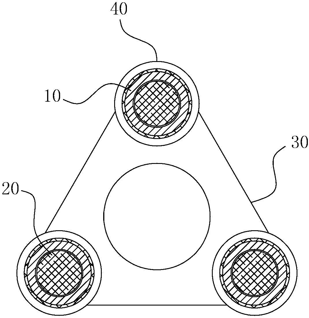
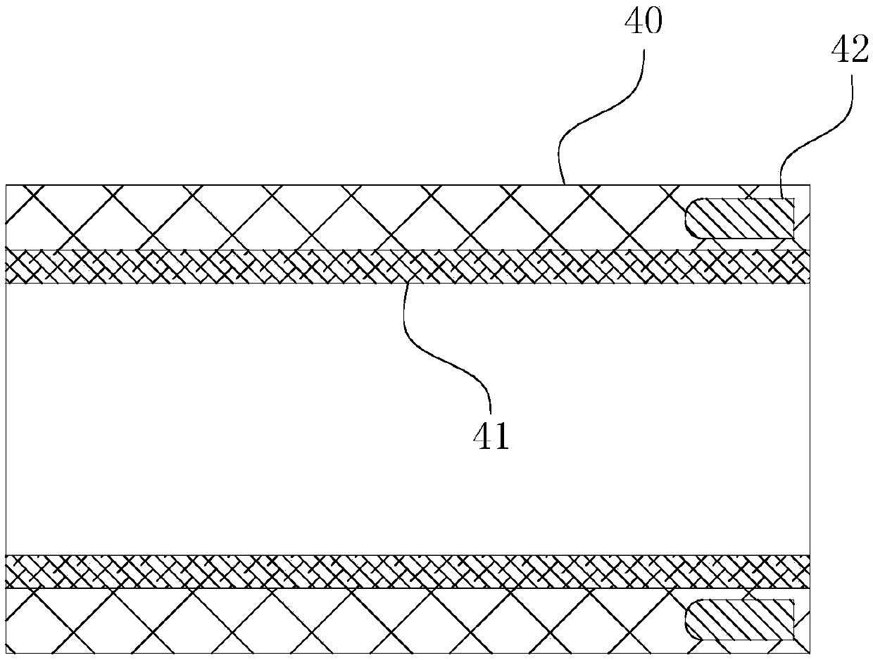
[0026] Concrete structure of the present invention refers to Figure 1-4 As shown, its main structure includes two triangular plate-shaped end sealing plates 30, three straight tube-shaped magnetic suction tubes 10, three magnetic rods as magnets 20, and six groups of cleaning cleaning tools with a gel layer or felt layer 41 on the inner ring surface. Ring 40. in:

[0027] The corner ends of the two end sealing plates 30 are all smoothly transitioned, while the three magnetic suction tubes 10 are in the shape of Figure 1-2 The shown triangular array is fixed between two end sealing plates 30 . Since the two end sealing plates 30 are parallel to each other, and the pipe ends of the three magnetic tubes 10 are welded to the corresponding end sealing plates 30, the lumens of the magnetic tubes 10 natural...


PUM


Abstract

The invention belongs to the field of lamination machine feeding assisting equipment, and particularly relates to a magnetic attraction type foreign matter removing device. The device comprises magnetic attraction pipes made of metal materials. Containing cavities used for containing magnets are formed by pipe cavities of the magnetic attraction pipes. End portion sealing plates made of metal materials are arranged at the two ends of each magnetic attraction pipe. The two end portion sealing plates are parallel to each other, and the maximum distance between the two end portion sealing platesis equal to the width of a hopper outlet pipeline of a lamination machine so that the two end portion sealing plates can be attracted and fixed to the outer pipe wall of the hopper outlet pipeline through magnetic attraction force of the magnets. The magnetic attraction pipes are in a straight barrel pipe shape, the position of the outer pipe wall of each magnetic attraction pipe is coaxially sleeved with a cleaning ring capable of axially moving along the outer pipe wall. The inner ring face of each cleaning ring is provided with a felt layer or a gel layer which is attached to the outer pipewall of the corresponding magnetic attraction pipe. By means of the device, the function of filtering out metal type foreign matter in raw materials at the feeding end position of the lamination machine can be achieved, and accordingly the delivery quality of a machined film finished product is effectively guaranteed while the service life of the machine is ensured.

Description

technical field [0001] The invention belongs to the field of feeding auxiliary equipment for laminating machines, and in particular relates to a magnetic suction type foreign matter removal device. Background technique [0002] Extrusion casting compound machine, commonly known as laminating machine in the industry, has the advantages of high automation, easy operation, high production speed, uniform coating thickness, high adhesion fastness, smooth coiling, environmental protection and pollution-free, and labor-saving It has developed maturely in Europe and the United States, and has gradually become popular in China in recent years. It is an inevitable trend to replace dry lamination and hot melt adhesive coating lamination. The working principle of the laminating machine is: after the plastic particles are plasticized by high temperature and screw, they are extruded in a molten state from the die lip of the laminating head in a linear shape, and after stretching, they are...

Claims


Application Information

Patent Timeline
Patent Type & Authority Applications(China)
IPC IPC(8): B29C47/10B29B13/10B29C41/36
CPCB29B13/10B29C41/36B29C48/287B29C48/288
Inventor 章威林镇海曹建国
Owner HUANGSHAN NOVEL
Why Eureka
Try Eureka