
Centrifugal rotor filter device with by-pass branch pipe

A centrifugal rotor and filter technology, used in the installation/connection of lubricant purification devices, lubricating parts, pressure lubricants, etc., can solve the problems of not meeting the requirements of light weight, poor oil return, and poor oil return. , to achieve the effect of occupying less space, ensuring smooth oil return, and reducing the weight of the device

Pending Publication Date: 2018-04-03
MANNHUMMEL FILTER SHANGHAI
View PDF0 Cites 2 Cited by
  • Summary
  • Abstract
  • Description
  • Claims
  • Application Information

AI Technical Summary

Problems solved by technology

[0003] In the application, although the size of the oil return pipeline and the layout of the oil inlet and outlet of the engine block meet the requirements, some oil return problems still occur
This is because during the oil return process, due to the violent movement of the oil, many small air bubbles will be formed, and the filtered oil will continuously bring the small air bubbles into the oil tank, so that the internal pressure of the centrifugal rotor filter housing is lower than the pressure of the oil tank, forming Relatively negative pressure, resulting in poor oil return
The usual way to solve this problem is to add an auxiliary oil return device to assist the oil return through compressed air, but this will greatly increase the cost and does not meet the requirements of light weight

Method used


Image

  • Centrifugal rotor filter device with by-pass branch pipe
  • Centrifugal rotor filter device with by-pass branch pipe
  • Centrifugal rotor filter device with by-pass branch pipe

Examples


Embodiment 1

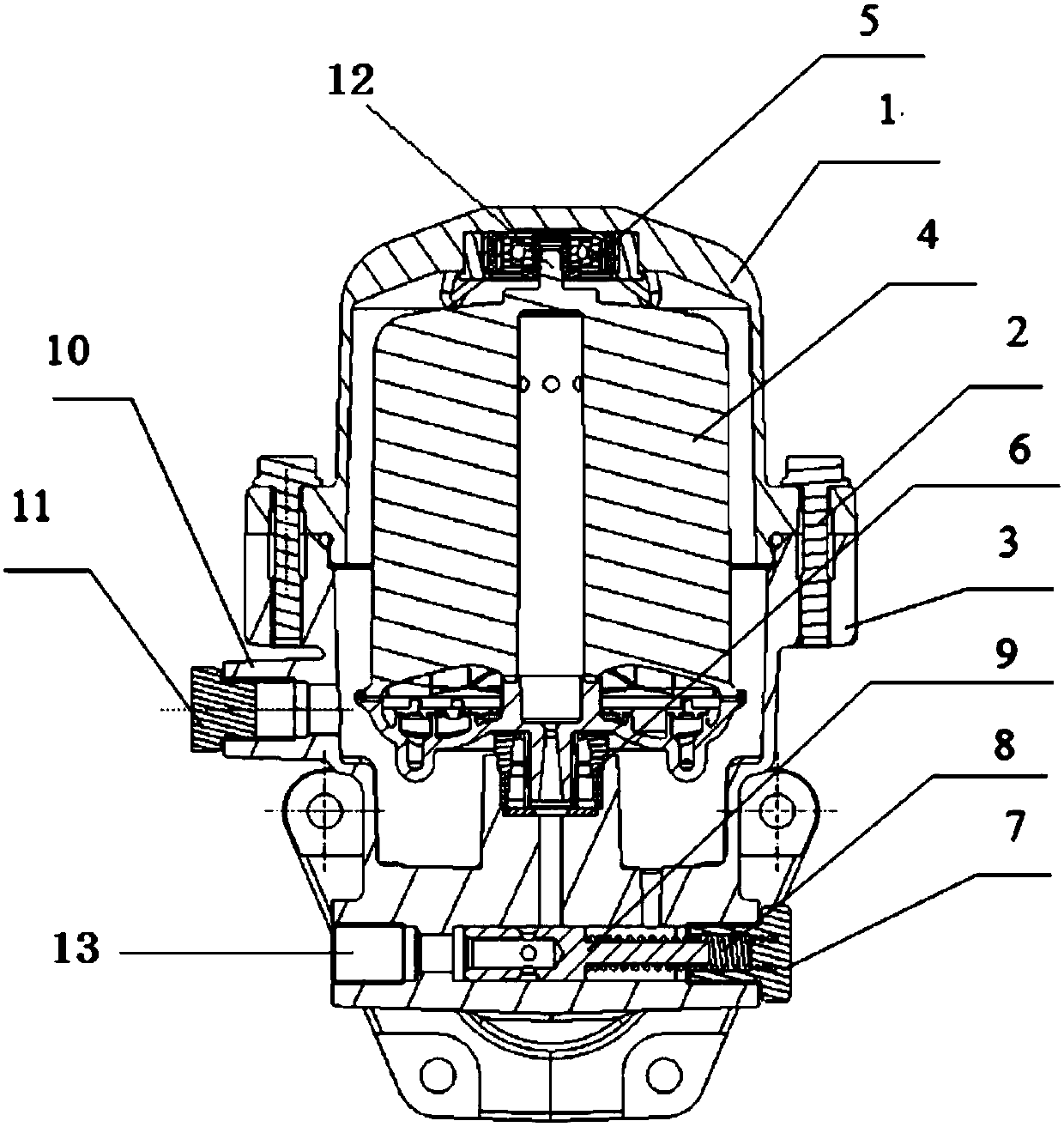
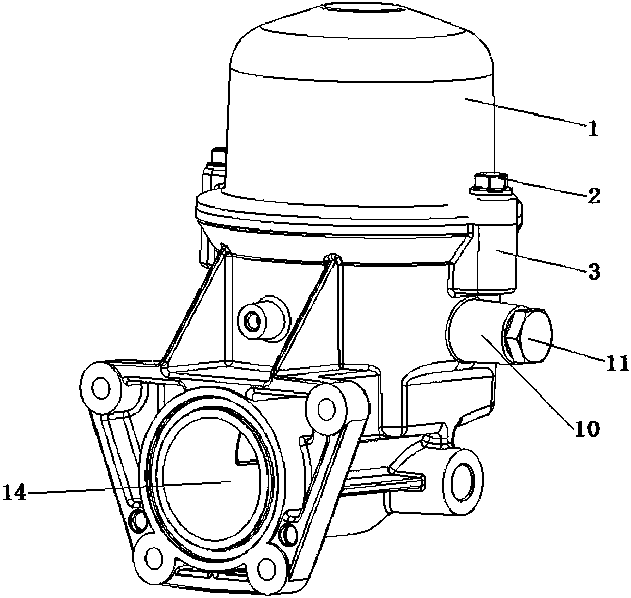
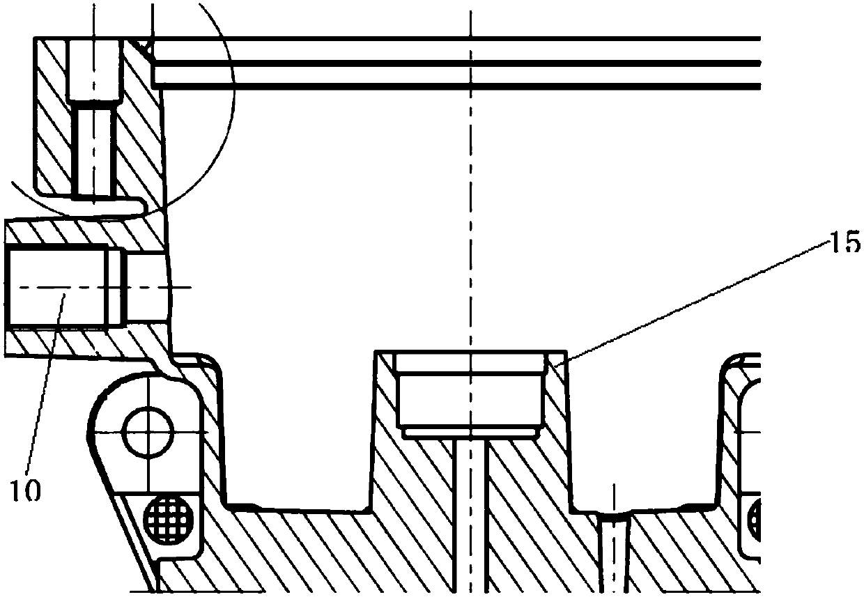
[0020] A centrifugal rotor filter unit with a bypass branch such as Figure 1-3 As shown, it includes an upper cover 1, a lower casing 3 and a rotor 4. The upper cover 1 is connected to the lower casing 3 through bolts 2, and the rotor 4 is fixed in the upper cover 1 and the lower casing 3 through the upper bearing 5 and the lower bearing 6. , the middle part of the upper and lower ends of the rotor 4 is provided with a rotating shaft 12, the rotating shaft at the upper end is connected to the upper bearing 5, the rotating shaft at the lower end is connected to the lower bearing 6, the bottom of the lower housing 3 is provided with an oil inlet pipeline 13, and a shut-off valve 9 is arranged in the oil inlet pipeline 13 , the cut-off valve 9 is connected to the spring 8, the spring 8 is fixed by the second plug 7, the lower housing 3 is provided with a bypass branch pipe 10, the bypass branch pipe 10 communicates with the centrifugal rotor filter, and the bypass branch pipe 10 ...


PUM

PropertyMeasurementUnit
Lengthaaaaaaaaaa

Abstract

The invention relates to a centrifugal rotor filter device with a by-pass branch pipe. The centrifugal rotor filter device comprises an upper cover, a lower shell and a rotor. The upper cover is connected with the lower shell through a bolt. The rotor is fixed to the upper cover and the interior of the lower shell through an upper bearing and a lower bearing. The bottom of the lower shell is provided with an oil inlet pipeline. The oil inlet pipeline is internally provided with a cut-off valve. The lower shell is provided with the by-pass branch pipe. The by-pass branch pipe communicates withthe interior of a centrifugal rotor filter. Compared with the prior art, the occupied space of the centrifugal rotor filter device is small, using of an auxiliary oil-return device is avoided, and thecentrifugal rotor filter device is suitable for a variety of models; the device is convenient to maintain, the rotor is only needed to be maintained during maintaining, the problem that oil returningis not smooth is easy to find, and maintenance difficulty is reduced; and according to the centrifugal rotor filter device, energy saving is achieved, the weight is reduced, the lightweight requirement is met, and smooth oil returning of the centrifugal rotor filter can be ensured without the use of additional power.

Description

technical field [0001] The invention relates to a centrifugal rotor filter device, in particular to a centrifugal rotor filter device with a bypass branch pipe. Background technique [0002] The centrifugal rotor filter is a filter device that uses the centrifugal force generated by the high-speed rotation of the rotor to make the impurities in the oil adhere to the inner wall of the rotor and separate the impurities from the oil. The oil pump extracts the oil from the oil tank and sends it to the centrifugal rotor filter, and the oil is sprayed out from the nozzle of the rotor to generate a reaction force to promote the rotation of the rotor. Normally, the flow and pressure delivered to the rotor are the key factors affecting the performance of the centrifugal rotor filter, and the layout and size of the oil return line are the key points affecting the normal operation of the centrifugal rotor filter. [0003] In the application, although the size of the oil return pipelin...

Claims


Application Information

Patent Timeline
IPC IPC(8): F01M11/03
CPCF01M11/03
Inventor 蒋兴
Owner MANNHUMMEL FILTER SHANGHAI
Learn More