Automobile engine thermal management system modeling and control method

A technology of thermal management system and automobile engine, applied in the direction of cooling of engine components, machine/engine, engine, etc.

Active Publication Date: 2018-04-03
JILIN UNIV
View PDF4 Cites 24 Cited by
  • Summary
  • Abstract
  • Description
  • Claims
  • Application Information

AI Technical Summary

Problems solved by technology

Among them, the water jacket and coolant heat transfer coefficient model solves the modeling problem of forced convection heat transfer coefficient in irregular pipelines

Method used


Image

  • Automobile engine thermal management system modeling and control method
  • Automobile engine thermal management system modeling and control method
  • Automobile engine thermal management system modeling and control method

Examples


Embodiment Construction

[0197] The control of the engine thermal management system described in the present invention is realized through software co-simulation, and the software adopts Matlab / Simulink and GT-Power. Among them, GT-Power software is a commercial engine one-dimensional simulation software, the main function is to provide a high-fidelity engine thermal management system model, instead of the real engine thermal management system as the controlled object. MATLAB / Simulink software is used to build the controller and observer.

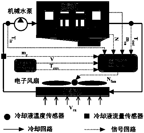
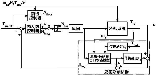
[0198] Functionally, the present invention includes the following parts: an inverse dynamics feed-forward controller module, a Smith predictor module, a PD feedback controller module, and an engine thermal management system module. The role of each part is explained in detail below:

[0199] The inverse dynamics feed-forward controller module calculates the fan speed to achieve the target coolant temperature according to the current measurement signal as the feed-...


PUM


Abstract

The invention relates to an automobile engine thermal management system modeling and control method, and belongs to the technical field of control. The aim is to provide an engine thermal management system dynamic modeling method and a water temperature control method. In the system dynamic modeling method, an accurate heating power model of an air cylinder to an inner wall, a heat exchange coefficient model of a water jacket and cooling liquid and a radiating power model of a radiator are built. The research method of the method comprises the following steps that according to the structure, the principle and measurable signals of an engine thermal management system, a system dynamic model is built; seen from the heat convection heat exchange and radiation heat exchange mechanisms, three intermediate variables in the dynamic model are derived; a system inverse dynamic model is derived according to the system dynamic model; a Smith predictor is designed according to the system dynamic model; and a PD feedback controller is designed. The dynamic model of the engine thermal management system is accurately built, and the control accuracy is improved.

Description

technical field [0001] The invention belongs to the technical field of control. Background technique [0002] The engine thermal management system is based on the structure of the traditional engine cooling system, and electrifies the main components: fans, water pumps, thermostats, etc., to realize the on-demand supply of coolant and cooling air, and can solve the traditional engine cooling system. Under normal circumstances, the phenomenon of engine overcooling or overheating caused by unreasonable operation of engine accessories, and at the same time reduce the power loss of accessories, thereby improving the economy and emission of the engine. [0003] Traditional engine cooling systems mostly use mechanical fans, which are mainly divided into two types: [0004] 1. Direct drive fan. The fan is rigidly connected to the engine crankshaft through a pulley, and the fan speed is proportional to the engine speed. [0005] 2. Clutch fan. There are mainly silicon oil clutch...

Claims


Application Information

Patent Timeline
Patent Type & Authority Applications(China)
IPC IPC(8): F01P7/16F01P11/00F01P11/14G06F17/50
CPCF01P7/16F01P11/00F01P11/14F01P2007/168G06F30/17
Inventor 吕良胡云峰史少云许志国陈虹
Owner JILIN UNIV
Why Eureka
Try Eureka