
Method for converting evanescent wave into traveling wave

A wave conversion and traveling wave technology, applied in optical components, instruments, optics, etc., can solve problems such as inability to obtain objects, collection, and small details, and achieve the effects of avoiding great loss, simple processing technology, and improving efficiency

Inactive Publication Date: 2018-04-03
WUHAN UNIV
View PDF4 Cites 16 Cited by
  • Summary
  • Abstract
  • Description
  • Claims
  • Application Information

AI Technical Summary

Problems solved by technology

Traditional optical imaging systems are limited by the diffraction limit because only traveling waves are collected on the imaging surface, and cannot obtain smaller details of objects. In many fields of modern technology, such as biomedical microscopic imaging, optical lithography, ultra-high density Optical storage, etc., hope to obtain imaging of objects beyond the diffraction limit, which requires not only collecting traveling waves but also evanescent waves on the imaging surface
At present, there have been related reports on the realization of super-resolution imaging in the near field, and there is also a super-resolution imaging technology (photon tunneling microscope) that converts evanescent waves into traveling waves by point-by-point scanning. However, how to realize parallel super-resolution imaging in the far field is still a challenge. A difficult problem, the main difficulty lies in how to collect the high-frequency detail information of the object carried by the evanescent wave in the far field

Method used


Image

  • Method for converting evanescent wave into traveling wave
  • Method for converting evanescent wave into traveling wave
  • Method for converting evanescent wave into traveling wave

Examples


Embodiment Construction

[0028] Below by embodiment, in conjunction with accompanying drawing, technical scheme of the present invention is described further in detail:

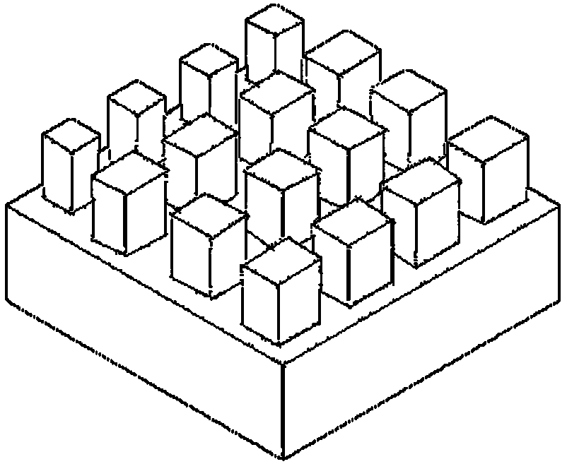
[0029] Such as figure 1 As shown, it is a schematic diagram of the geometry of the polarization-independent nanobrick array that realizes the function of converting evanescent waves into traveling waves in the present invention. Nanobricks of different sizes are arranged in an array in a specific way to provide different wave vector changes for incident light waves. Therefore, the evanescent wave of the spatial wave vector component within a certain range is converted into a traveling wave and emitted.

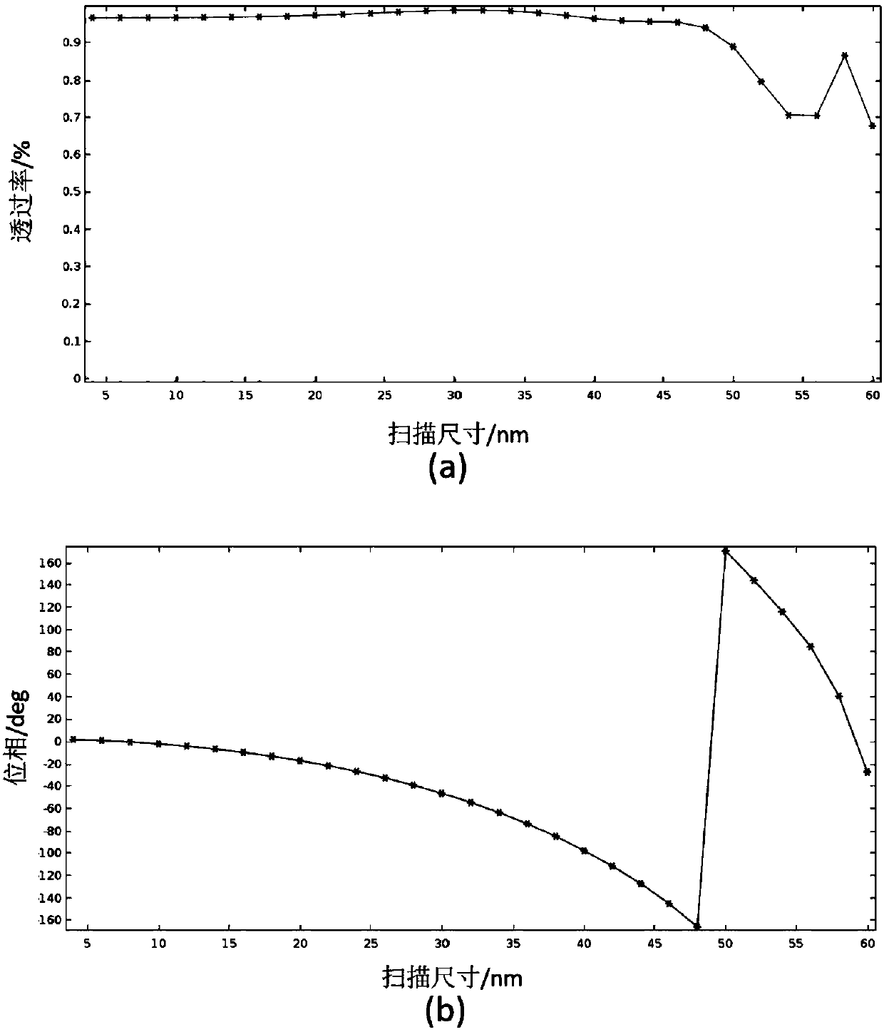
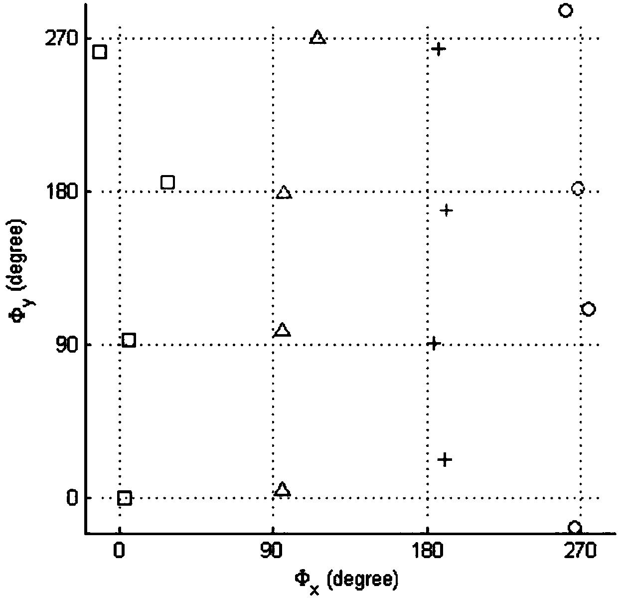
[0030] Taking a metasurface material composed of a 4*4 polarization-independent nanobrick array as an example, it is set to provide 2.5k polarized incident light waves in the x direction. 0 The amount of change in the transverse wave vector allows the incident light waves polarized in the y direction to pass through without being mo...


PUM


Abstract

The invention provides a method for converting an evanescent wave into a traveling wave. The method is implemented by the aid of a super-surface grating formed by a polarization independent nano-brickarray. Size parameters of the length and the width of a nano-brick are adjusted, a phase gradient is designed, the super-surface grating is constructed, different transverse wave vector variation ofpolarized incident light waves along the directions of a long axis and a short axis of the nano-brick can be achieved, so that the evanescent wave is converted into the traveling wave, the traveling wave is transmitted to a far field, and super-resolution imaging is achieved. The super-surface formed by the nano-brick array has the advantages of high integration and transmittance, relatively simple machining process and the like and is applied to the fields such as biomedicine microscopy imaging, optical lithography and ultrahigh-density optical memory.

Description

technical field [0001] The invention belongs to the field of optical imaging, and in particular relates to a method for converting evanescent waves into traveling waves by using a metasurface material composed of polarization-independent nano-brick arrays. Background technique [0002] According to the theory of Fourier optical imaging, light waves from an object can be decomposed into monochromatic plane waves with different spatial frequencies, in which the lateral spatial frequency represents the detailed information of the object, and the larger the lateral spatial frequency, the corresponding lateral wave vector is also bigger. In this way, according to the size of the transverse wave vector, the light wave is divided into a traveling wave that can propagate to the imaging surface and an evanescent wave whose propagation distance is on the order of wavelength. Traditional optical imaging systems are limited by the diffraction limit because only traveling waves are coll...

Claims


Application Information

Patent Timeline
IPC IPC(8): G02B27/58G02B27/00
CPCG02B27/0012G02B27/58
Inventor 郑国兴魏然李子乐何平安毛庆洲李松邓联贵戴琦王宇吴伟标
Owner WUHAN UNIV
Learn More