Load flow calculation method and device for combined electricity-heat systems, equipment and storage medium

A joint system and power flow calculation technology, applied in the field of energy systems, can solve problems such as not considering the dynamic process of the heating system, unfavorable multi-energy coordination of multi-energy systems, and not considering the coupling relationship between other energy systems and heating systems

Active Publication Date: 2018-04-03
SHENZHEN GRADUATE SCHOOL TSINGHUA UNIV
View PDF2 Cites 7 Cited by
  • Summary
  • Abstract
  • Description
  • Claims
  • Application Information

AI Technical Summary

Problems solved by technology

[0004] Existing studies only focus on the heating system, without considering the coupling relationship between other energy systems and the heating system. This analysis method makes the integrated energy system (such as the electric-thermal coupling system) less flexible, which is not conducive to the multi-energy system. multi-energy synergy
At present, in the multi-energy system, the steady-state model is used for power flow calculation, or the simplified model is used for power flow calculation. Among them, the steady-state model regards the heating system with dynamic process and energy storage capacity as a system without dynamic process, and does not consider The dynamic process of transmission in the heating system ignores the transmission delay, which makes the calculation results inaccurate; and the simplified model can reduce the difficulty of model establishment, but reduces the flexibility and adjustment range of the actual multi-energy system. Not conducive to the improvement of economic benefits and efficiency

Method used


Image

  • Load flow calculation method and device for combined electricity-heat systems, equipment and storage medium
  • Load flow calculation method and device for combined electricity-heat systems, equipment and storage medium
  • Load flow calculation method and device for combined electricity-heat systems, equipment and storage medium

Examples


Embodiment 1

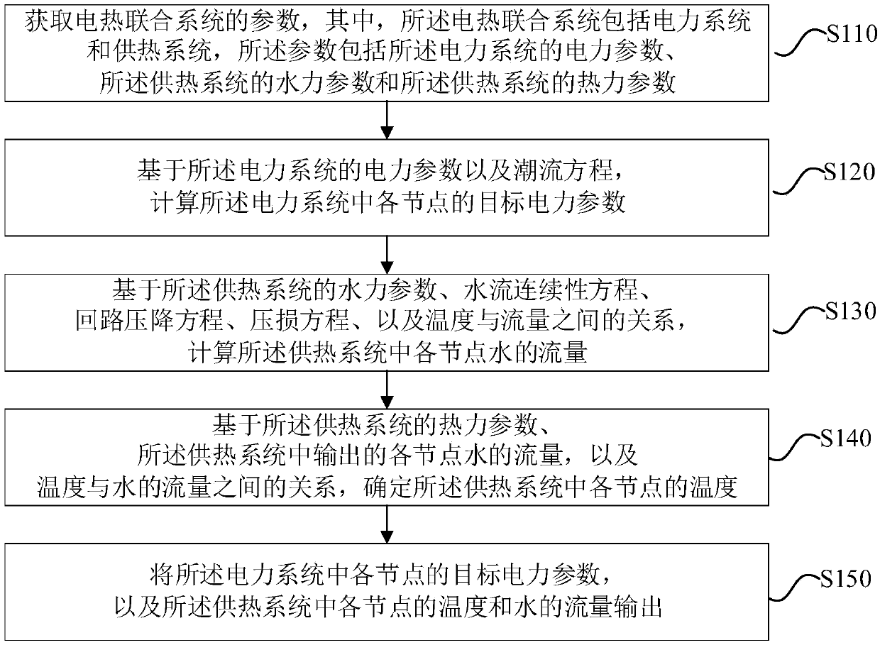
[0031] figure 1 It is a flow chart of a power flow calculation method for a combined electric heating system provided by Embodiment 1 of the present invention. This embodiment is applicable to the analysis and calculation of an integrated energy system with combined electric heating. This method can be provided by the embodiment of the present invention The power flow calculation device of the integrated electric heating system can be implemented by means of software and / or hardware, and can generally be integrated in the computer equipment for monitoring and analyzing the comprehensive energy system. Such as figure 1 As shown, the method of this embodiment specifically includes:

[0032] S110. Acquire parameters of the combined electric and heat system, wherein the combined electric and heat system includes a power system and a heating system, and the parameters include electric parameters of the power system, hydraulic parameters of the heating system, and the heating syste...

Embodiment 2

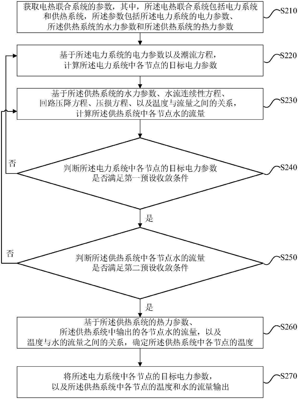
[0066] figure 2 It is a flow chart of a power flow calculation method for a combined electric heating system provided by Embodiment 2 of the present invention. This embodiment is optimized on the basis of the foregoing embodiments.

[0067] S210. Acquire parameters of the combined electric heating system, wherein the combined electric heating system includes an electric power system and a heating system, and the parameters include electric parameters of the electric power system, hydraulic parameters of the heating system, and the heating system thermal parameters.

[0068] S220. Calculate target power parameters of each node in the power system based on the power parameters and power flow equations of the power system.

[0069] S230. Calculate the flow of water at each node in the heating system based on the hydraulic parameters of the heating system, the water flow continuity equation, the loop pressure drop equation, the pressure loss equation, and the relationship betwee...

Embodiment 3

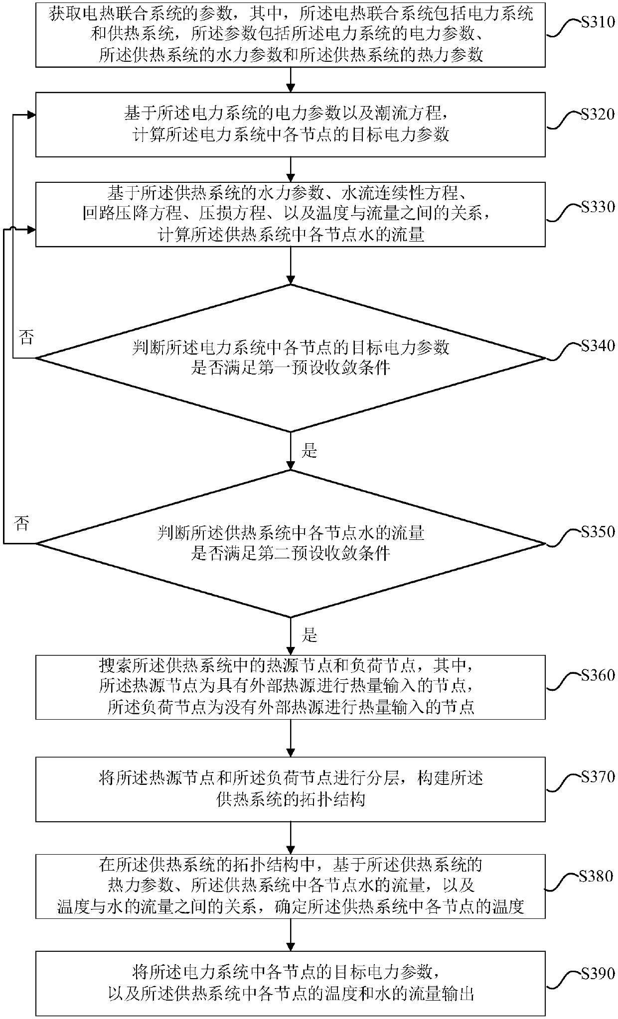
[0094] Figure 3a It is a flow chart of a power flow calculation method for a combined electric heating system provided by Embodiment 3 of the present invention, and this embodiment is embodied on the basis of the foregoing embodiments.

[0095] S310. Acquire parameters of the combined electric heating system, wherein the combined electric heating system includes an electric power system and a heating system, and the parameters include electric parameters of the electric power system, hydraulic parameters of the heating system, and the heating system thermal parameters.

[0096] S320. Calculate target power parameters of each node in the power system based on the power parameters and power flow equations of the power system.

[0097] S330. Calculate the flow of water at each node in the heating system based on the hydraulic parameters of the heating system, the water flow continuity equation, the loop pressure drop equation, the pressure loss equation, and the relationship be...


PUM


Abstract

Embodiments of the invention disclose a load flow calculation method and device for combined electricity-heat systems, equipment and a storage medium. The method comprises the following steps of: obtaining parameters of a combined electricity-heat system; calculating a target electric power parameter of each node in an electric power system on the basis of electric power parameters of the electricpower system and a load flow equation; calculating a water flow rate of each node in a heat supply system on the basis of hydraulic parameters of the heat supply system, a water flow continuity equation, a loop pressure drop equation, a pressure loss equation and a relationship between temperatures and flow rates; determining a temperature of each node in the heat supply system on the basis of thermal parameters of the heat supply system, the water flow rate of each node in the heat supply system, and the relationship between temperatures and water flow rates; and outputting the target electric power parameter of each node in the electric power system and the temperature and water flow rate of each node in the heat supply system. According to the method and device, the equipment and the storage medium, the correctness of the load flow calculation of combined electricity-heat systems can be improved and flexibility is provided for the scheduling of electric power systems.

Description

technical field [0001] The present invention relates to the field of energy systems, in particular to a power flow calculation method, device, equipment and storage medium of a combined electric heating system. Background technique [0002] With the increasingly severe energy and environmental problems, in order to improve the overall efficiency of energy and the ability to accommodate renewable energy, there is an increasingly urgent need for multi-type energy interconnection integration and complementary integration. How to effectively calculate the distribution of multi-energy sources is of great significance to the investment planning and operation decision-making of multi-energy systems. [0003] For power systems, power flow is the distribution of voltage (including amplitude and phase angle), active power, reactive power, etc. throughout the power system, and is the basis of power system scheduling. Power flow calculation is a basic electrical calculation to study th...

Claims


Application Information

Patent Timeline
Patent Type & Authority Applications(China)
IPC IPC(8): G06F19/00G06Q50/06
CPCG06Q50/06G16Z99/00
Inventor 孙宏斌郭庆来王彬秦鑫沈欣炜
Owner SHENZHEN GRADUATE SCHOOL TSINGHUA UNIV
Why Eureka
Try Eureka