Aorta covered stent

A stent-graft and main stent technology, applied in stents and other directions, can solve problems such as difficulty in placing guidewires, inability to mass-produce, blood flow channel occlusion, etc. Effect

Pending Publication Date: 2018-04-06
SUZHOU INNOMED MEDICAL DEVICE +1
View PDF1 Cites 2 Cited by
  • Summary
  • Abstract
  • Description
  • Claims
  • Application Information

AI Technical Summary

Problems solved by technology

However, such a design has the following limitations: ①During use, the chimney stent is located between the aortic stent-graft and the inner wall of the aorta, causing the aortic stent-graft to not stick firmly to the wall, thereby causing endoleaks; ②due to The elastic tension of the aortic stent graft is stronger than that of the chimney stent, and it is easy to compress the chimney stent for a long time during use, resulting in a smaller cross-section of the blood flow channel formed by the chimney stent or occlusion of the blood flow channel, thereby affecting the blood circulation of important branch vessels and causing the body Ischemia of related parts; ③During the operation, due to the special structure between the chimney stent and the aortic covering, it is difficult for the doctor to place the

Method used


Image

  • Aorta covered stent
  • Aorta covered stent
  • Aorta covered stent

Examples


no. 1 approach

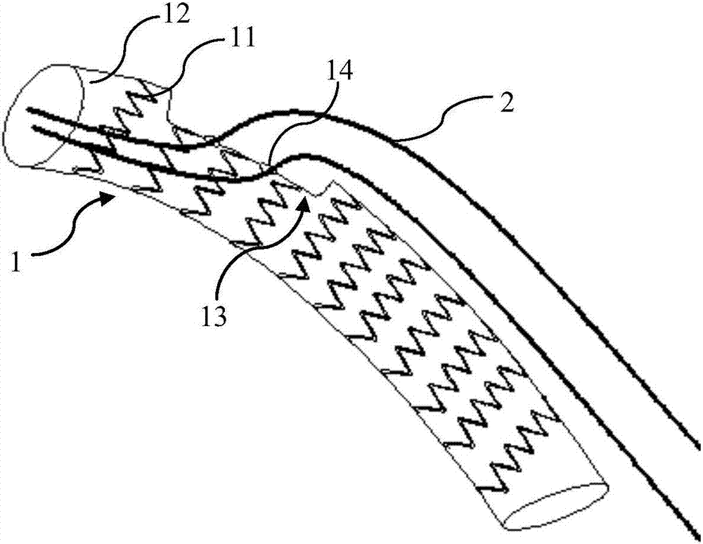
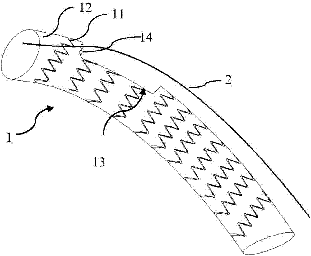
[0027] Figure 1a , Figure 1b It is a schematic diagram of an example of an aortic stent graft according to an embodiment of the present invention.

[0028] Such as Figure 1a and Figure 1b As shown, the aortic stent graft includes a main stent 1, and the main stent 1 includes a main stent body 11, which has a recess 13 and the main stent body is covered with a main stent membrane 12, and the main stent body 13 is The membrane of the main stent is provided with two through holes 14 for the branch artery stent (not shown in FIG. 1 ) to extend into the main stent. The aortic stent graft also includes one or two guide wires 2 , one end of the guide wire 2 extends into the main stent through the through hole 14 , and is used to guide the branch artery stent to pass through the through hole 14 and extend into the main stent.

[0029] In this embodiment, for example, there may be one recess 13 on the main stent body, and two through holes 14 are provided on the main stent membra...

no. 2 approach

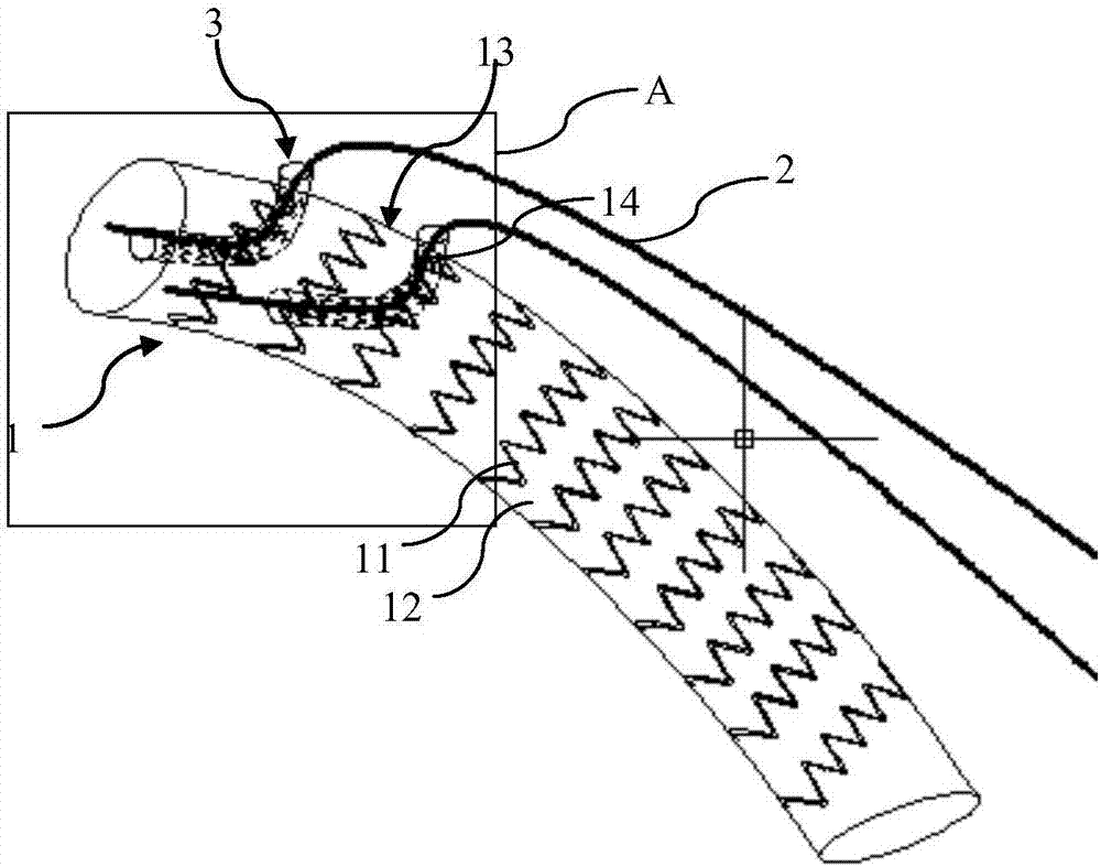
[0042] Figure 2a , Figure 2b is a schematic structural view of an aortic stent graft according to another embodiment of the present invention; image 3 yes Figure 2a The enlarged schematic diagram of part A in ; Figure 4a , Figure 4b , Figure 4c It is a schematic diagram of an aortic stent graft according to another embodiment of the present invention when used in an aortic vessel.

[0043] Such as Figure 2a to Figure 4c As shown, the aortic stent graft includes a main stent 1, and the main stent 1 includes a main stent body 11, which has a recess 13 and the main stent body is covered with a main stent membrane 12, and the main stent body 13 is The main stent membrane is provided with 2 through holes 14 for the branch artery stent 4 (see Figure 4a to Figure 4c shown) into the inside of the main bracket. The aortic stent-graft also includes two film-covered connecting stents 3 , one end of the connecting stent 3 extends into the main stent through the through ho...


PUM

PropertyMeasurementUnit
Lengthaaaaaaaaaa
Lengthaaaaaaaaaa
Lengthaaaaaaaaaa

Abstract

The invention provides an aorta covered stent. The aorta covered stent comprises a main stent, the main stent comprises a main stent body, the main stent body is provided with at least one concave part, a main stent membrane covers the main stent body, and the main stent membrane of the concave part is provided with at least one through hole for a branch arterial stent to stretch into the main stent. The aorta covered stent can be used for treating aortic aneurysm or aortic dissection, internal hemorrhage can be effectively reduced, branch blood flow clogging can be effectively prevented, andthe operation is also convenient.

Description

technical field [0001] The invention relates to an aortic covered stent for treating aortic aneurysm or aortic dissection. Background technique [0002] In recent years, minimally invasive endovascular treatment techniques in vascular surgery have made great progress, and vascular stents have been widely used in the treatment of systemic vascular diseases. According to the distribution of lesions, different vascular stents can be mainly used for peripheral vascular lesions, small artery lesions, and aortic lesions; depending on the pathology, different vascular stents can be used for vascular traumatic lesions, vascular stenosis or restenosis Wait. [0003] For aortic lesions, such as aortic aneurysm and aortic dissection, aortic stent grafts are mainly used at present. [0004] In the prior art, in order not to affect the blood supply of important branch vessels while isolating the breach, a chimney stent is usually added outside the aortic stent graft to form a blood sup...

Claims


Application Information

Patent Timeline
IPC IPC(8): A61F2/91
CPCA61F2/91A61F2002/821A61F2002/823
Inventor 魏继昌龚霄雁张小明周卫超刘浩
Owner SUZHOU INNOMED MEDICAL DEVICE
Why Eureka
Try Eureka