
Accurate measuring device and method for pouring time for sand mold casting and molding structure

A pouring time, sand casting technology, applied in casting molding equipment, configuration of indicating equipment/measuring equipment, casting equipment, etc., can solve the difference of a few seconds, sometimes even tens of seconds, and cannot accurately verify the rationality of the pouring system , Inability to correctly check the rising speed of molten iron, etc., to achieve the effect of narrowing the variation range, measuring the pouring time accurately and reliably, and guiding the production.

Inactive Publication Date: 2018-04-06
HIMILE MECHANICAL SCI & TECH (SHANDONG) CO LTD
View PDF0 Cites 0 Cited by
  • Summary
  • Abstract
  • Description
  • Claims
  • Application Information

AI Technical Summary

Problems solved by technology

[0004] However, in this measurement method, the pouring time obtained requires the recorder to judge the start and end of the timing, which is greatly affected by factors such as ambient light, personnel vision, and the sequence of pulling out the sprue basin. In fact, the pouring time measured by the same casting varies widely. Large, sometimes the difference is a few seconds, sometimes even tens of seconds. If this is used to determine the pouring time, it is very imprecise, and the subjective factor affects a very large proportion
[0005] At the same time, the pouring time obtained by the above measurement process is not simply the pouring time of the casting, but the total time of the entire pouring process including the casting; and the inaccurate measurement of the pouring time will lead to the inability to correctly check the molten iron. Process parameters such as rising speed, minimum residual pressure head (all molten iron fills the cavity, minimum height from the highest point of the casting to the liquid level of the sprue cup) and other process parameters cannot accurately verify the rationality of the gating system

Method used


Image

  • Accurate measuring device and method for pouring time for sand mold casting and molding structure
  • Accurate measuring device and method for pouring time for sand mold casting and molding structure
  • Accurate measuring device and method for pouring time for sand mold casting and molding structure

Examples


Embodiment Construction

[0038] The present invention will be further described below in conjunction with the accompanying drawings and embodiments.

[0039] It should be pointed out that the following detailed description is exemplary and intended to provide further explanation to the present application. Unless defined otherwise, all technical and scientific terms used herein have the same meaning as commonly understood by one of ordinary skill in the art to which this application belongs.

[0040] It should be noted that the terminology used here is only for describing specific implementations, and is not intended to limit the exemplary implementations according to the present application. As used herein, unless the context clearly dictates otherwise, the singular is intended to include the plural, and it should also be understood that when the terms "comprising" and / or "comprising" are used in this specification, they mean There are features, steps, operations, means, components and / or combinatio...


PUM


Abstract

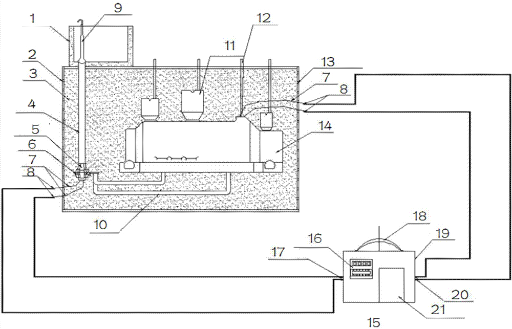
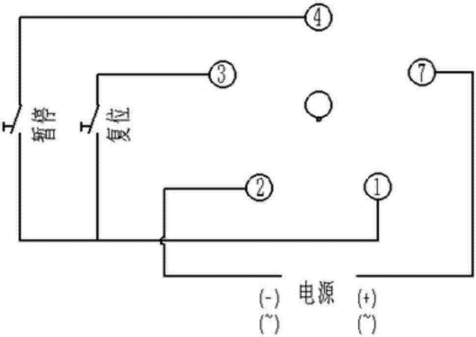
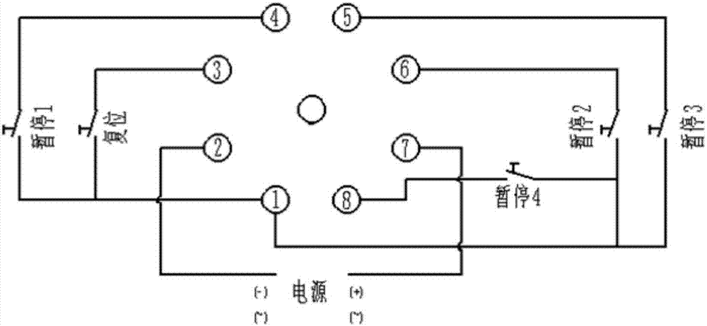
The invention discloses a device, method and molding structure for accurately measuring the pouring time of sand casting. The device includes conductive parts and a timer. The conductive parts include at least two groups. The bottom end of the road is connected to the timer as the trigger end for starting timing; another set of conductive parts is set at the sand riser and connected to the timer as the trigger end for stopping timing; by recording the trigger conduction time corresponding to the two sets of conductive parts , to get the pouring time. In the measurement process of the present invention, the conductivity of the metal pouring liquid is used for measurement, and the interference of influencing factors such as ambient light, personnel's field of view, and the sequence of pulling out and plugging the sprue basin is eliminated, and the measurement result is more objective and accurate.

Description

technical field [0001] The invention relates to a device, method and molding structure for accurately measuring the pouring time of sand casting. Background technique [0002] For a long time, the pouring time of sand casting is an important technical parameter, which has an important influence on the quality of castings. The pouring time is related to the quality and structure of the casting, the process conditions of the casting mold, the type of alloy and the selected pouring system. The current casting process design determines the pouring time generally based on various empirical formulas and charts, and is usually determined according to the quality (weight) of the casting. [0003] In the actual casting casting process, the measurement of pouring time is mostly when the molten metal (take molten iron as an example) is poured into the sprue basin from the ladle (or the nozzle plug is unplugged after the molten iron reaches a certain level in the sprue basin) to start ...

Claims


Application Information

Patent Timeline
IPC IPC(8): B22D2/00B22C9/02
CPCB22D2/00B22C9/02
Inventor 申加友王向阳宫耀宇秦虎张良栾旭
Owner HIMILE MECHANICAL SCI & TECH (SHANDONG) CO LTD
Learn More