Fuel cell power system for vehicle
A fuel cell and power system technology, applied in the direction of fuel cells, fuel cell additives, battery/fuel cell control devices, etc., can solve problems such as long start-up waiting time, complex structure, and too many components, and achieve a reduction in system The effect of occupying volume and weight, simplifying the power system, and reducing system energy consumption
- Summary
- Abstract
- Description
- Claims
- Application Information
AI Technical Summary
Problems solved by technology
Method used
Image
Examples
Embodiment 1
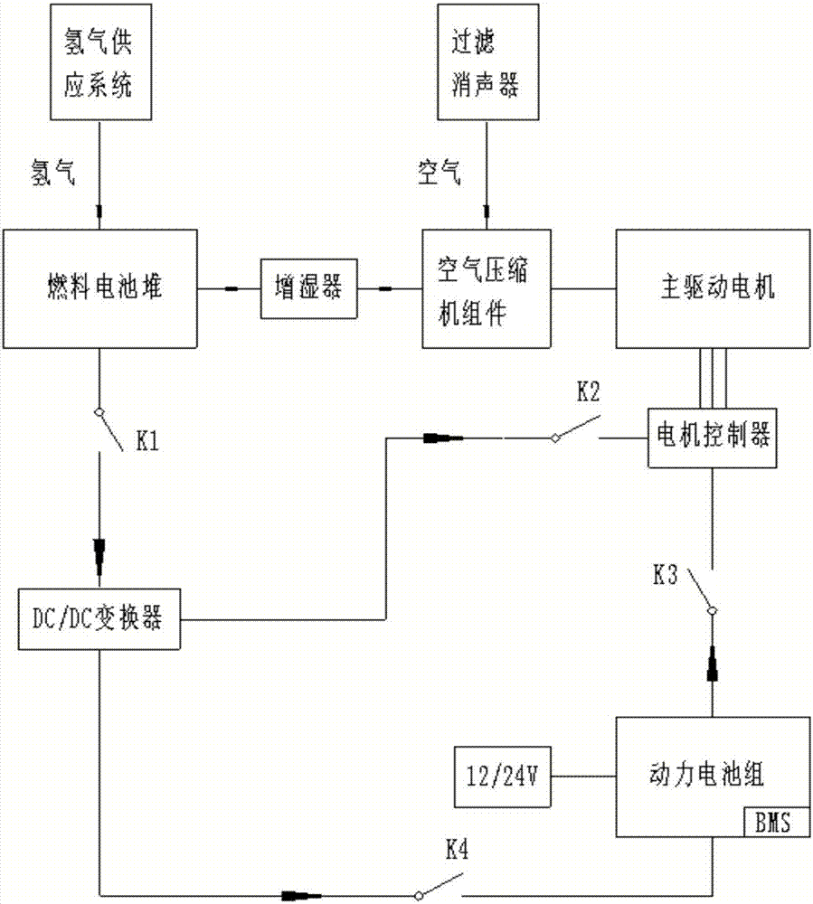
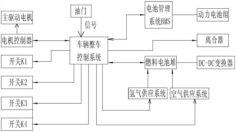
[0034] Such as figure 1 , figure 2 , image 3 As shown, the fuel cell power system for a vehicle of the present invention includes: a fuel cell stack, a hydrogen supply system, an air supply system, a DC / DC converter, a power battery pack, and a main drive motor system. The air supply system includes An air compressor assembly, a filter muffler and a humidifier. The main drive motor system includes a main drive motor and a motor controller. The main drive motor is a dual-shaft extension motor. One end is connected to the vehicle power transmission system and the other end is connected to air Compressor components, the main drive motor provides energy for the vehicle power transmission system and air compressor components.
[0035] A clutch is arranged between the biaxial extension motor and the air compressor assembly.
[0036] The air compressor assembly includes a compressor and a speed increaser.
[0037] The clutch is an electromagnetic clutch or a mechanical clutch with pneuma...
Embodiment 2
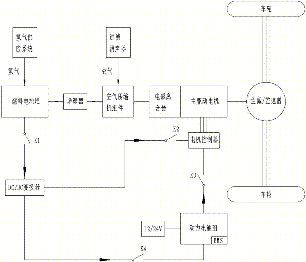
[0047] Such as Figure 4 As shown, the structure of this embodiment is basically the same as that of the first embodiment. The difference lies in: the vehicle power transmission system mainly includes a main reducer / differential; a gearbox is provided between the main drive motor and the vehicle power transmission system. The gearbox has a reverse gear position. The main drive motor is directly connected with the air compressor assembly, eliminating the clutch between the main drive motor and the air compressor assembly.
[0048] The vehicle adopts a cold start method when starting. The specific process is: when the vehicle power is turned on, the 12V / 24V low-voltage power output of the power battery pack provides low-voltage input for the vehicle control system and battery management system BMS, and the battery management system BMS controls the power battery The process of charging and discharging the battery; when the throttle signal is given, the switches K1, K2, and K4 are i...
Embodiment 3
[0052] Such as Figure 5 As shown, the structure of this embodiment is basically the same as that of the first embodiment. The difference lies in: the vehicle power transmission system mainly includes a main reducer / differential; an electromagnetic clutch is provided between the main drive motor and the vehicle power transmission system.
[0053] This embodiment is similar to the working conditions of the first embodiment. The difference is that a clutch is provided between the main drive motor and the main reducer / differential. When the clutch is disconnected, the vehicle can be warmed up. That is, when the vehicle is hot or idling, the switch K2 is in the open state, and the switches K1, K3, and K4 are in the closed state. The power battery pack provides energy to the main drive motor and drives the air compressor assembly to rotate to make the fuel cell stack The voltage is gradually increased to the operating voltage required by the system. When the fuel cell stack voltage re...
PUM
 Abstract
Description
Claims
Application Information
 - R&D
- Intellectual Property
- Life Sciences
- Materials
- Tech Scout
- Unparalleled Data Quality
- Higher Quality Content
- 60% Fewer Hallucinations
Browse by: Latest US Patents, China's latest patents, Technical Efficacy Thesaurus, Application Domain, Technology Topic, Popular Technical Reports.
© 2025 PatSnap. All rights reserved.Legal|Privacy policy|Modern Slavery Act Transparency Statement|Sitemap|About US| Contact US: help@patsnap.com


