Formwork trolley and sliding formwork construction method for utility tunnel cast-in-place concrete sliding formwork construction

A technology of integrated pipe gallery and formwork trolley, which is applied in artificial islands, water conservancy projects, infrastructure projects, etc., can solve the problems of high labor intensity, high construction cost, slurry leakage, etc. The effect of reducing the construction cost and the overall structure is simple

Pending Publication Date: 2018-04-06
CHENGDU JIANGONG ROAD & BRIDGE CONSTR
View PDF5 Cites 14 Cited by
  • Summary
  • Abstract
  • Description
  • Claims
  • Application Information

AI Technical Summary

Problems solved by technology

[0003] At present, the construction of underground comprehensive pipe gallery has been carried out on a large scale across the country. The existing construction methods of comprehensive pipe gallery mainly have the following problems: 1. Traditional construction with scaffolding formwork, low construction efficiency, long construction period, manual demolition The labor intensity of loading and transporting materials is high and the construction cost is high; 2. The ...

Method used


Image

  • Formwork trolley and sliding formwork construction method for utility tunnel cast-in-place concrete sliding formwork construction
  • Formwork trolley and sliding formwork construction method for utility tunnel cast-in-place concrete sliding formwork construction
  • Formwork trolley and sliding formwork construction method for utility tunnel cast-in-place concrete sliding formwork construction

Examples


Embodiment Construction

[0027] The present invention will be described in detail below in conjunction with the drawings.

[0028] In order to make the objectives, technical solutions, and advantages of the present invention clearer, the following further describes the present invention in detail with reference to the accompanying drawings and embodiments. It should be understood that the specific embodiments described here are only used to explain the present invention, but not to limit the present invention.

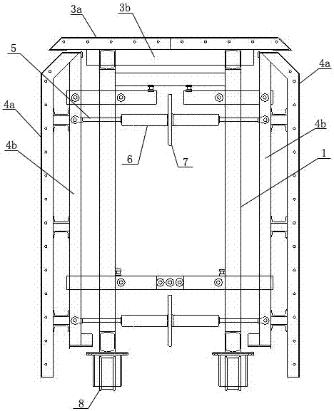
[0029] Such as Figure 1-4 As shown, a formwork trolley for the construction of cast-in-situ concrete slipforms in a comprehensive pipe gallery includes a formwork system, a trolley frame 1, a side support mechanism, a jacking mechanism, and a walking mechanism. The formwork system consists of a top module The top mold assembly is arranged directly above the trolley frame 1 and connected with the trolley frame 1, and the side mold assemblies are arranged on both sides of the trolley frame 1 and pa...


PUM


Abstract

The invention discloses a formwork trolley structure for utility tunnel cast-in-place concrete sliding formwork construction. The formwork trolley comprises a formwork system, a trolley frame, a lateral supporting mechanism, a jacking mechanism and a traveling mechanism. The formwork system is composed of a top formwork assembly and side formwork assemblies. The top formwork assembly is arranged over the trolley frame and connected with the trolley frame. The side formwork assemblies are arranged on the two sides of the trolley frame and connected with the trolley frame through the lateral supporting mechanism. According to the formwork trolley and the sliding formwork construction method, by means of mutual cooperation during pouring of a middle gallery wall of the utility tunnel and large set-shaped steel formworks on all the trolleys, a pouring space of the middle gallery wall of the tunnel is formed between the side formworks of the adjacent trolleys, in addition, the supporting reliability of the formwork structures is guaranteed through the actions of the lateral supporting mechanisms of the trolleys, formwork deformation in the pouring process of the middle gallery wall is avoided, the number of formwork seams is small, and the forming quality of the middle gallery wall is improved; and meanwhile, the formwork trolley is simple in overall structure, labor is saved, and the construction cost is reduced.

Description

Technical field [0001] The invention belongs to the technical field of building construction, and in particular relates to a formwork trolley and a slipform construction method for the construction of a comprehensive pipe gallery cast-in-place concrete slip form. Background technique [0002] The comprehensive pipe gallery project refers to the municipal shared tunnel built under the urban roads, which is used to centralize and place the power, communication, water supply, gas and other pipelines in the comprehensive pipe gallery to facilitate unified management and maintenance in the future to realize underground space Comprehensive utilization and resource sharing. [0003] At present, the construction of underground integrated pipe gallery has been carried out on a large scale nationwide. The existing construction method of integrated pipe gallery has the following problems: 1. The traditional scaffolding formwork is used for construction, the construction efficiency is low, the...

Claims


Application Information

Patent Timeline
IPC IPC(8): E02D29/045
CPCE02D29/045
Inventor 邓江云崔永胜江涛李伟刘江伟
Owner CHENGDU JIANGONG ROAD & BRIDGE CONSTR
Why Eureka
Try Eureka