Conduction cooling and milling knife for dry milling

A technology of conduction cooling and milling tools, which is applied in the direction of milling cutters, manufacturing tools, milling machine equipment, etc., which can solve the problems of short service life of milling tools, inability to add cutting fluid, and poor cooling effect, so as to reduce cutting temperature and reduce temperature , The effect of convenient assembly and disassembly

Pending Publication Date: 2018-04-13
NANJING COLLEGE OF INFORMATION TECH
View PDF0 Cites 5 Cited by
  • Summary
  • Abstract
  • Description
  • Claims
  • Application Information

AI Technical Summary

Problems solved by technology

However, for some special materials, such as carbon fiber materials, cutting fluid cannot be added during milling, and only dry cutting can be performed
[0003] At present, only the air cooling method of blowing cold air to the tool can be used in the process of dry cutting. The cooling effect is not good, the processing efficiency is low, and the service life of the milling tool is short.

Method used


Image

  • Conduction cooling and milling knife for dry milling
  • Conduction cooling and milling knife for dry milling
  • Conduction cooling and milling knife for dry milling

Examples


Embodiment Construction

[0021] In order to make the purpose, technical solution and advantages of the present invention clearer, the technical solution of the present invention will be clearly and completely described below in conjunction with the accompanying drawings and specific embodiments.

[0022] "Center", "vertical", "horizontal", "upper", "lower", "front", "rear", "left", "right", "vertical", "horizontal" described in the present invention , "top", "bottom", "inner", "outer" and other indicated orientations or positional relationships are based on the orientations or positional relationships shown in the drawings, and are only for the convenience of describing the invention and simplifying the description, rather than indicating Or imply that the device or element referred to must have a specific orientation, be constructed and operated in a specific orientation, and therefore should not be construed as limiting the invention (unless otherwise specified).

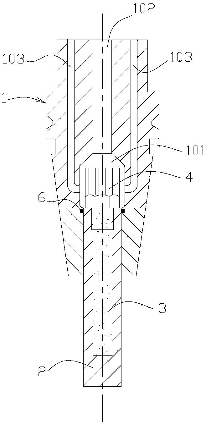
[0023] refer to figure 1 , a cond...


PUM


Abstract

The invention provides a conduction cooling milling tool for dry milling, which includes a handle and a milling cutter installed at the lower end of the handle, and also includes a heat conduction cooling rod and a heat sink; the heat conduction cooling rod is arranged at the center of the milling cutter , the outer surface of the heat conduction cooling rod is attached to the inner surface of the milling cutter, the upper end of the heat conduction cooling rod protrudes from the milling cutter, and the outer peripheral surface of the extension end is fitted with a number of cooling fins; the center of the handle is provided with The heat exchange cavity, the coolant inlet channel and the coolant outflow channel connected with the heat exchange cavity, the extended end of the heat conduction cooling rod and the heat sink welded on the extended end are all accommodated in the heat exchange cavity. The thermal conductivity of the thermally conductive cooling rod is higher than that of the milling cutter. The invention utilizes the heat conduction principle to realize the cooling of the cutting tool during the dry cutting and milling process, so as to realize the effective milling of the dry cutting material.

Description

technical field [0001] The invention belongs to the technical field of machining, in particular to a conduction cooling milling tool for dry milling. Background technique [0002] In the milling process, adding cutting fluid to the milling part has the functions of cooling, lubricating, cleaning, cutting and rust prevention, so cutting fluid is widely used in the milling process. However, for the processing of some special materials, such as carbon fiber materials, cutting fluid cannot be added during milling, and only dry cutting can be performed. [0003] At present, in the process of dry cutting, only the air cooling method of blowing cold air to the tool can be used. The cooling effect is not good, the processing efficiency is low, and the service life of the milling tool is short. Contents of the invention [0004] In view of the above-mentioned problems in the prior art, the present invention provides a conduction cooling milling tool for dry cutting, which utilizes...

Claims


Application Information

Patent Timeline
Patent Type & Authority Applications(China)
IPC IPC(8): B23C5/28
CPCB23C5/28
Inventor 任长春马云鹏张颖利黄丽娟丁友生
Owner NANJING COLLEGE OF INFORMATION TECH
Why Eureka
Try Eureka