
Piercing device and method for beverage capsules

A processing device and capsule technology, which is applied in metal processing and other directions, can solve problems such as deformation, increased production cost, and impact on punching process production efficiency and yield, so as to reduce production cost, improve production efficiency, and smooth the punching area Effect

Active Publication Date: 2018-04-17
无锡鼎加弘思饮品科技有限公司
View PDF6 Cites 0 Cited by
  • Summary
  • Abstract
  • Description
  • Claims
  • Application Information

AI Technical Summary

Problems solved by technology

In some capsules, a piercing device is installed inside the capsule to avoid food problems such as mildew or pollution caused by the repeated use of the external guide needle, which is difficult to clean. The beverage flows out of the capsule through a suitable outlet. Because the material of the capsule shell is usually made of high-quality The barrier multi-layer material is composited and then blow-molded. It has a soft texture and strong toughness. Therefore, in order to ensure that the puncture guide inside the capsule cannot pierce the capsule shell, it is usually punched at the bottom of the capsule shell first, and then used The solution is to heat seal the hole with aluminum foil. However, the current punching device is easy to form serrations, wrinkles or even serious deformation during the punching process, which seriously affects the production efficiency and yield of the industrial mass production of the punching process, resulting in production The cost has risen sharply

Method used


Image

  • Piercing device and method for beverage capsules
  • Piercing device and method for beverage capsules
  • Piercing device and method for beverage capsules

Examples


Embodiment Construction

[0023] The present invention will be described in further detail below in conjunction with the accompanying drawings and examples. The following examples are only descriptive, not restrictive, and cannot limit the protection scope of the present invention.

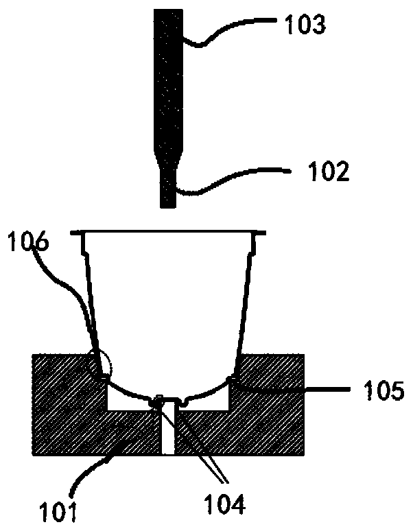
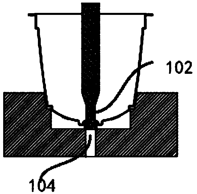
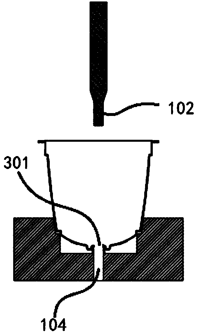
[0024] figure 1 Shown is a state diagram of the beverage capsule punching processing device according to the present invention before punching, figure 1 Only the punch and the bottom die related to the important improvement points of the present invention are shown in the figure. Although other structures such as drive motors and power supplies are not shown, drive motors, stepping motors, servo motors, etc. are commonly used in industrial production lines. device, and the punching processing device of the present invention does not involve changes in driving and transport devices, and thus only shows the setting relationship of the punch and the bottom die involved in achieving the improved punching effect. Such as figu...


PUM


Abstract

The invention discloses a piercing device for beverage capsules. The piercing device for beverage capsules comprises a bottom mold and a punch, wherein the bottom mold comprises a capsule positioninggroove and a piercing positioning structure; the capsule positioning groove is an annular inner groove; a side wall of the capsule positioning groove consists of a vertical main positioning plane anda secondary positioning plane of which the top is inclined outwards to form an oblique plane; the main positioning plane is projected out of the secondary positioning plane so that the capsule positioning groove is step-shaped; the piercing positioning structure is arranged in the center of the bottom surface of the capsule positioning groove, and is a hollow cylinder which is projected out of thebottom surface of the capsule positioning groove; the punch comprises a cylindrical head and a tail; the outer diameter of the cylindrical head is smaller than the inner diameter of the piercing positioning structure; the tail is fixedly connected with a piercing power mechanism; and the vertical projection of the punch drops in the piercing positioning structure. The invention further provides apiercing method. A pierced region of a capsule shell pierced on the basis of the piercing device and method is flat and smooth, and thus, the piercing device and method for beverage capsules are suitable for efficient industrial production of an assembly line.

Description

technical field [0001] The invention relates to the technical field of beverage production equipment, in particular to a beverage capsule punching processing device and a punching processing method. Background technique [0002] Capsule-based rapid beverage preparation systems are rapidly developing in the field of beverage preparation technologies such as coffee and tea, which complete beverage preparation by inserting capsules containing granular beverage preparation ingredients (such as ground coffee) into beverage preparation devices followed by rapid extraction. The device typically injects water into the capsule, where the beverage-making ingredients are dissolved or mixed into the water to form the beverage, and a deflector needle pierces the bottom of the capsule to deflect the beverage into a container. In some capsules, a piercing device is installed inside the capsule to avoid food problems such as mildew or pollution caused by the repeated use of the external gui...

Claims


Application Information

Patent Timeline
Patent Type & Authority Applications(China)
IPC IPC(8): B26F1/02B26D7/01
CPCB26D7/01B26F1/02
Inventor 卢应志丁阳唐鸣
Owner 无锡鼎加弘思饮品科技有限公司
Learn More