Two-degree-of-freedom guide rail for ellipsoidal glass bulb detection

A degree of freedom and ellipsoidal technology, which is applied in measuring devices, optical testing of flaws/defects, and material analysis through optical means, can solve the problem of difficult to guarantee machining accuracy and difficult to process large-sized ellipsoidal guide rails and ellipsoidal guide rails. Difficulty and other problems, to achieve the effect of uniform light source and uniform light emission

Active Publication Date: 2018-04-17
HARBIN INST OF TECH
View PDF5 Cites 1 Cited by
  • Summary
  • Abstract
  • Description
  • Claims
  • Application Information

AI Technical Summary

Problems solved by technology

[0006] In order to solve the problem that the current ellipsoidal guide rail is very difficult to process, and the processing accuracy is difficult to guarantee, it is difficult to process large-sized ellipsoidal guide rails, and further provides a dual-degree-of-freedom guide rail for the detection of ellipsoidal glass bulbs

Method used


Image

  • Two-degree-of-freedom guide rail for ellipsoidal glass bulb detection
  • Two-degree-of-freedom guide rail for ellipsoidal glass bulb detection
  • Two-degree-of-freedom guide rail for ellipsoidal glass bulb detection

Examples


specific Embodiment approach 1

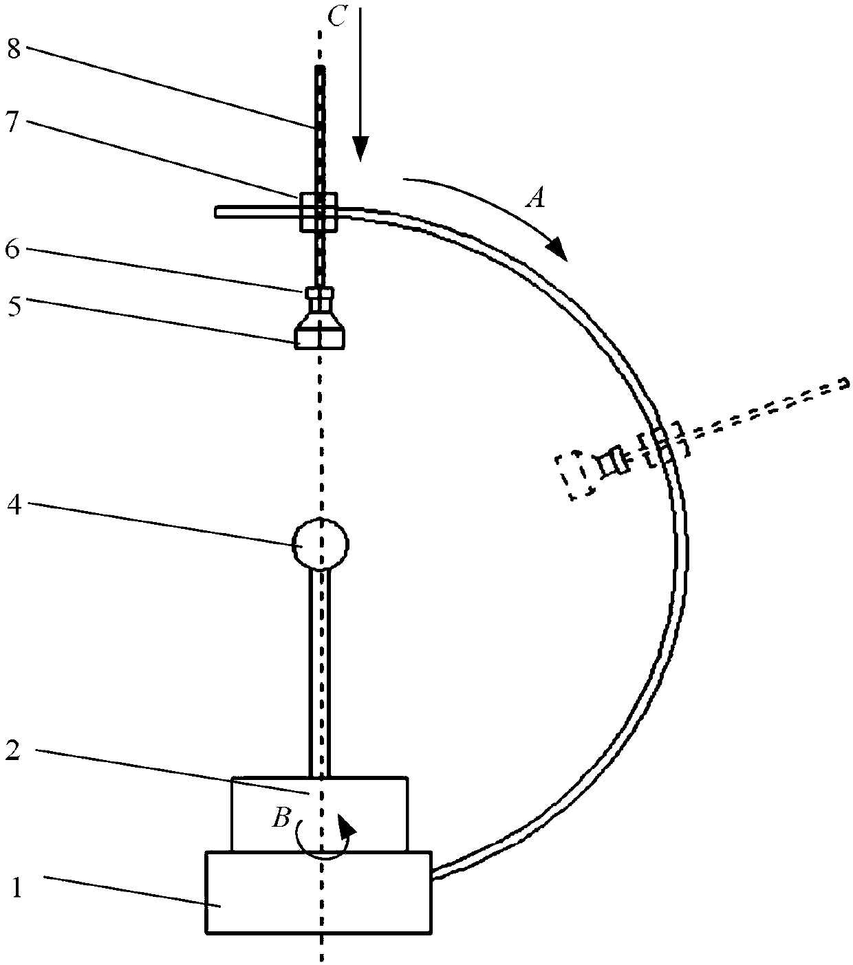
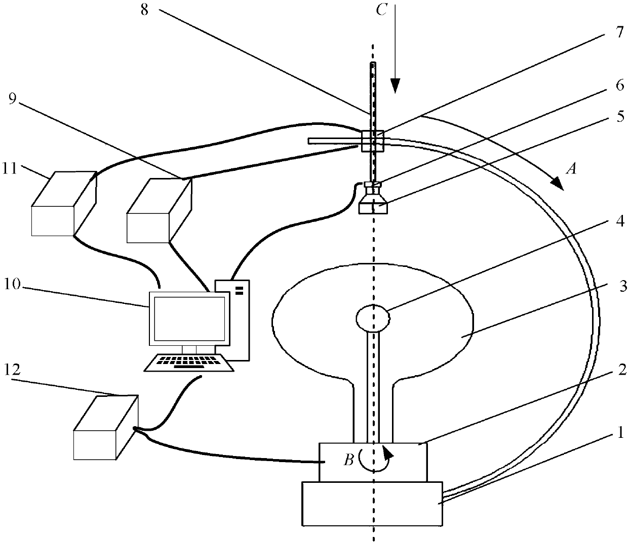
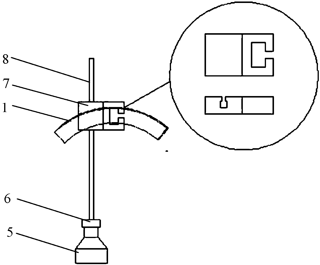
[0020] Specific implementation mode one: as Figure 1~4 As shown, the dual-degree-of-freedom guide rail used for the detection of an ellipsoidal glass bulb in this embodiment includes a guide rail assembly 1, a bidirectional connection slider 7 and a camera connection pole 8; the outline of the guide rail assembly 1 is semicircular, and the bidirectional connection slider 7 is provided with a first groove and a second groove, the two-way connection slider 7 is installed on the guide rail assembly 1 through the first groove and the two-way connection slider 7 is slidingly connected with the guide rail assembly 1, and the two-way connection slider 7 is The first groove and the second groove are arranged perpendicular to each other, the camera connecting rod 8 is inserted into the second groove of the two-way connecting slider 7 , and the camera connecting rod 8 points to the center of the guide rail assembly 1 .

[0021] Since the processing of the ellipsoidal guide rail is diff...

specific Embodiment approach 2

[0027] Specific implementation mode two: as figure 1 and figure 2 As shown, the guide rail assembly 1 of this embodiment includes a guide rail body and a guide rail fixing seat, and the lower end of the guide rail body is fixedly mounted on the guide rail fixing seat. With such a design, the guide rail can be fixed, and the circular turntable 2 of the ellipsoid glass bulb detection device can also be installed. Other components and connections are the same as those in the first embodiment.

specific Embodiment approach 3

[0028] Specific implementation mode three: as figure 1 and figure 2 As shown, the cross section of the guide rail body in this embodiment is rectangular. Designed in this way, it is convenient for the two-way connection slider 7 to slide on the guide rail body, which is convenient for processing. Other compositions and connections are the same as those in Embodiment 1 or 2.


PUM


Abstract

The invention discloses a two-degree-of-freedom guide rail for ellipsoidal glass bulb detection and relates to a two-degree-of-freedom guide rail. The problem that a large-size ellipsoidal glass bulbis difficult to machine because the conventional ellipsoidal glass bulb is high in processing difficulty and the machining precision is difficult to ensure is solved. An outline of a guide rail assembly is semicircular, a first groove and a second groove are formed in a connecting slide block, the connecting slide block is arranged on the guide rail assembly by the first groove and connected withthe guide rail assembly in a sliding manner; the first groove and the second groove in the connecting slide block are mutually perpendicular to each other; a camera connecting support rod is insertedinto the second groove of the connecting slide block; and the camera connecting support rod points at a center of a circle of the guide rail assembly. The two-degree-of-freedom guide rail disclosed bythe invention is applied to the ellipsoidal glass bulb detection.

Description

technical field [0001] The invention relates to a dual-degree-of-freedom guide rail, in particular to a dual-degree-of-freedom guide rail of a surface quality detection device for an ellipsoidal glass bulb, and belongs to the technical fields of surface quality detection and automatic detection. Background technique [0002] A photomultiplier tube is a vacuum electronic device that converts weak light signals into electrical signals. Photomultiplier tubes are used in optical measuring instruments and spectroscopic analysis instruments. It can measure extremely weak radiation power with a wavelength of 200-1200 nanometers in low-level photometry and spectroscopy. The emergence of scintillation counters has expanded the application range of photomultiplier tubes. The development of laser detection instruments is closely related to the use of photomultiplier tubes as effective receivers. The launch and image transmission of TV movies are also inseparable from photomultiplier...

Claims


Application Information

Patent Timeline
IPC IPC(8): G01N21/88
CPCG01N21/8851G01N2021/8887
Inventor 陆敏王治乐王华林林菲刘敬琪赵峰周程颢朱瑶
Owner HARBIN INST OF TECH
Why Eureka
Try Eureka