Translucent structure

A technology of light transmittance and structure, applied in the directions of optics, light source, electric light source, etc., can solve the problem of reducing the visual recognition of images, and achieve the effect of suppressing the reduction of visual recognition and low haze

Active Publication Date: 2020-08-25
AGC INC
View PDF12 Cites 0 Cited by
  • Summary
  • Abstract
  • Description
  • Claims
  • Application Information

AI Technical Summary

Problems solved by technology

[0008] On the other hand, when the antiglare-treated substrate is placed on the display surface of an image display device, there is a problem that glare occurs on the display surface due to the unevenness, and the visibility of the image decreases.

Method used


Image

  • Translucent structure
  • Translucent structure
  • Translucent structure

Examples


no. 1 approach }

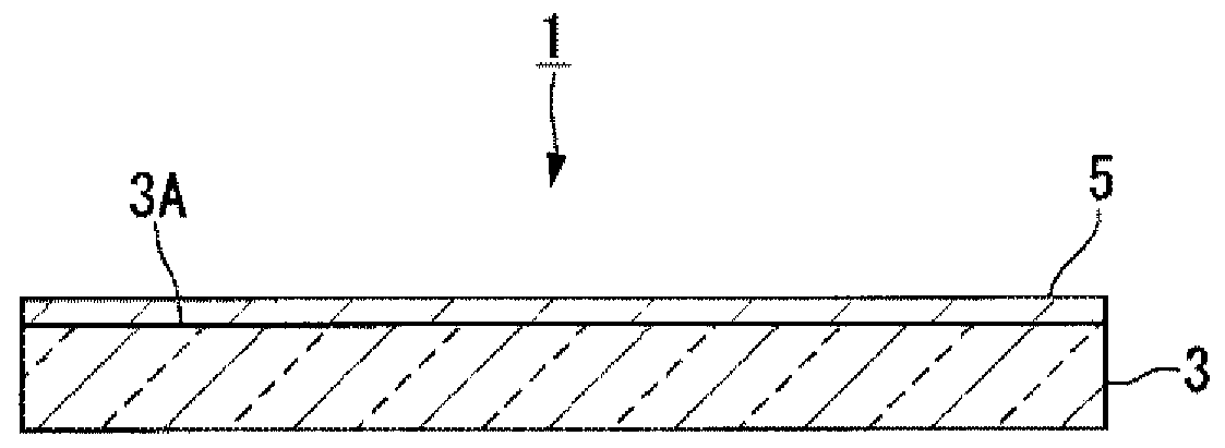
[0058] figure 1 Among them, the translucent structure 1 of this embodiment has the translucent base material 3 and the antiglare layer 5 formed on the first surface 3A. The antiglare layer 5 has a concavo-convex structure on the surface. The surface of the antiglare layer 5 constitutes the surface of the translucent structure 1 . Therefore, the translucent structure 1 has a concavo-convex structure on the surface. It should be noted, figure 1 In this example, the ratio of the thickness of the anti-glare layer 5 to the thickness of the light-transmitting base material 3 is larger than the actual ratio for the sake of convenience.

[0059] (translucent substrate)

[0060] As the translucent base material 3, any base material may be used as long as it can transmit visible light, and a transparent base material is preferable. Transparency in the light-transmitting substrate 3 means that light in the wavelength range of 400 nm to 1100 nm transmits an average of 80% or more (av...

no. 2 approach }

[0184] Figure 4 It is a schematic cross-sectional view showing the translucent structure 2 according to the second embodiment of the present invention. Figure 5 It is a diagram illustrating the relationship between the surface shape of the light-transmitting structure 2 , its smoothed image, and an image obtained as a difference of their XYZ data.

[0185] The translucent structure 2 of the present embodiment has a translucent base material 4 . The translucent substrate 4 has a concavo-convex structure on the first surface 4A. The first surface 4A of the translucent substrate 4 constitutes the surface of the translucent structure 2 . Therefore, the translucent structure 2 has a concavo-convex structure on the surface.

[0186] The light-transmitting base material 4 is the same as the light-transmitting base material 3 of the first embodiment except that the first surface has a concavo-convex structure, and the preferred form is also the same.

[0187] The uneven structur...

no. 3 approach }

[0199] Figure 6 It is a cross-sectional view schematically showing the translucent structure 6 according to the third embodiment of the present invention. Figure 7 It is a cross-sectional view schematically illustrating the structure near the surface of the translucent structure 6 . In addition, in the embodiment shown below, the same code|symbol is attached|subjected to the component corresponding to the said embodiment, and detailed description is abbreviate|omitted.

[0200] The translucent structure 6 of the present embodiment has a translucent substrate 3 , an antiglare layer 5 formed on the first surface 3A of the translucent substrate 3 , and an antireflection layer formed on the antiglare layer 5 7 (functional layer), and the water and oil repellent layer 9 (functional layer) formed on the anti-reflection layer 7. The antireflection layer 7 and the water and oil repellent layer 9 each have a concavo-convex structure on the surface similarly to the antiglare layer 5...


PUM

PropertyMeasurementUnit
diameteraaaaaaaaaa
sizeaaaaaaaaaa
surface roughnessaaaaaaaaaa

Abstract

Provided is a light-transmitting structure with low haze and low sparkle. A light-transmitting structure having a concavo-convex structure on its surface, the concavo-convex structure including a surface shape (a) obtained by measuring the concavo-convex structure with a laser microscope, the diameter of which is 1 μm at the height of the bearing portion + 0.05 μm For the first convex portion 5a above, the average value of the diameter of the first convex portion 5a is 1.000 μm to 16.000 μm, and the surface shape (a) is filtered by image processing software to obtain a smooth image (b), which is obtained from the surface shape ( In the image (c) obtained by subtracting the XYZ data of the smoothed image (b) from the XYZ data of a), a plurality of convex portions are dispersed, when the height of the mounting portion is set to 0, the plurality of convex portions include The second convex portion 5b having a diameter of 0.4 μm or more at a height of 0.01 μm, and the density of the second convex portion 5b is 0.023 pieces / μm 2 ~7.210 pieces / μm 2 , and the ratio of the total area of ​​the cross-section at the height of 0.01 μm of the second convex portion 5b is 0.900% to 90.000%.

Description

technical field [0001] The present invention relates to an anti-glare translucent structure having low haze and low glare properties. Background technique [0002] Image display devices (liquid crystal displays, organic electroluminescence (EL) displays, plasma displays, etc.) installed in various devices (TVs, personal computers, smartphones, mobile phones, vehicles, etc.), indoor lighting (fluorescent lamps, etc.) When external light such as sunlight and sunlight is reflected on the display surface, the visibility is reduced due to the reflected image. [0003] In order to suppress reflection of external light, an anti-glare treatment is performed on the surface of a substrate (such as a glass plate) constituting a display surface of an image display device. The anti-glare treatment is a process of providing unevenness on the surface and scattering incident light by the unevenness. Due to the diffuse reflection of incident light, the reflection image becomes unclear, and...

Claims


Application Information

Patent Timeline
Patent Type & Authority Patents(China)
IPC IPC(8): G02B5/02B32B3/30B32B7/023G02B1/113G02B1/115H01L51/50H05B33/02
CPCG02B1/113G02B1/115G02B5/0221G02B5/0247G02B5/0278G02B1/14G02B1/18B32B17/06H10K77/10H10K50/854B32B3/30G02B1/11G02B5/0205
Inventor 竹田洋介池田徹府川真
Owner AGC INC
Why Eureka
Try Eureka