Ultrasonic scalpel bit, ultrasonic vibration transmission module and ultrasonic haemostatic and cutting system

A technology of ultrasound and cutter head, which is applied in the field of medical devices, can solve the problems of poor effect, achieve the effect of increasing the effective length, improving the hemostasis effect, and improving the characteristics of amplitude and pressure distribution

Pending Publication Date: 2018-04-20
北京水木天蓬医疗设备有限公司
View PDF5 Cites 3 Cited by
  • Summary
  • Abstract
  • Description
  • Claims
  • Application Information

AI Technical Summary

Problems solved by technology

[0004] The invention provides an ultrasonic cutter head, an ultrasonic vibration transmission component and an ultrasonic hemostasis and cutting system to solve the problem of poor cutting and hemostasis effects on biological tissues such as large blood vessels in the prior art

Method used


Image

  • Ultrasonic scalpel bit, ultrasonic vibration transmission module and ultrasonic haemostatic and cutting system
  • Ultrasonic scalpel bit, ultrasonic vibration transmission module and ultrasonic haemostatic and cutting system
  • Ultrasonic scalpel bit, ultrasonic vibration transmission module and ultrasonic haemostatic and cutting system

Examples


Embodiment approach 1

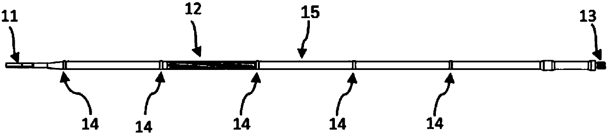
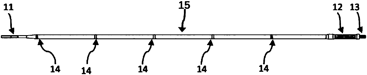
[0036] This embodiment discloses an ultrasonic cutter head 101, the structure of which is shown in Figure 1(a), Figure 1(b), Figure 1(c), Image 6 and Figure 8 As shown, it includes an ultrasonic tool tip 11, a waveguide 15, a connecting portion 13 and a vibration node boss 14, the ultrasonic tool tip 11 is arranged on the front side of the waveguide 15, the connecting portion 13 is arranged on the rear side of the waveguide 15, and the vibration node boss 14 Provided on the waveguide 15 , the ultrasonic blade tip 11 is bent laterally at the tip, and a vibration guide groove 12 is provided on the waveguide 15 . Among the above components, the ultrasonic blade tip 11 is used for cutting and hemostasis of the biological tissue 401, the vibration guide groove 12 is used to convert the longitudinal vibration of the ultrasonic transducer into longitudinal and torsional composite vibration, and the connecting portion 13 is used to connect the ultrasonic blade. The head is connecte...

Embodiment approach 2

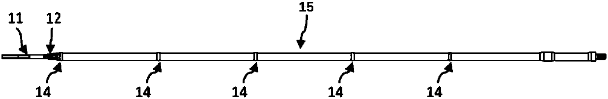
[0042] like Figure 8 As shown, this embodiment is different from the first embodiment in that the vibration guide groove is arranged on the waveguide 15 , and the vibration guide groove 12 of the ultrasonic tool head 101 is arranged on the ultrasonic tool tip 11 and is located at the rear end of the ultrasonic tool tip 11 . department. The above arrangement can further reduce the frictional heat generation effect between the vibration guide groove 12 and the lubricating cylinder 108 .

Embodiment approach 3

[0044] On the basis of the first or second embodiment, the present embodiment further defines the shape of the ultrasonic tool tip 11 of the ultrasonic tool head 101 . That is, the ultrasonic tip 11 includes a tapered width feature in addition to being laterally curved at the tip. For example, the gradient width feature can be a trapezoid gradient width feature, the top view of which is shown in Figure 9(a), the front end of the ultrasonic tool tip 11 has a larger front end and a narrower rear end width; its side view is shown in Figure 9(b) Show. The above design can change the mass distribution law of the ultrasonic blade tip 11 along the vibration axis, thereby improving the amplitude and pressure distribution characteristics of the ultrasonic blade tip 11 along the vibration axis, and further improving the temperature of the ultrasonic blade tip 11 during coagulation or cutting of the biological tissue 401. Uniformity and improved hemostasis.


PUM


Abstract

Disclosed is an ultrasonic haemostatic and cutting system. The ultrasonic haemostatic and cutting system comprises an ultrasonic vibration transmission module, an ultrasonic scalpel bit (101) of the ultrasonic vibration transmission module comprises an ultrasonic scalpel tip (11), a connecting part (13), vibration node bosses (14) and a waveguide unit (15), wherein the ultrasonic scalpel tip (11)is arranged in front of the waveguide unit (15); the connecting part (13) is arranged at the rear of the waveguide unit (15); the vibration node boss (14) is arranged on the waveguide unit (15); the sharp end of the ultrasonic scalpel tip (11) is laterally bent; the ultrasonic scalpel bit (101) is provided with a vibration guide groove (12). By designing the ultrasonic scalpel bit into a bent shape and converting longitudinal ultrasonic vibration into longitudinal and torsional compound vibration, the ultrasonic haemostatic and cutting system can improve temperature uniformity inside of cut orcoagulated tissues and further improve the haemostatic and cutting efficiency and security.

Description

technical field [0001] The invention relates to the technical field of medical devices, in particular to an ultrasonic cutter head, an ultrasonic vibration transmission assembly and an ultrasonic hemostasis and cutting system. Background technique [0002] Compared with ordinary scalpels and other energy surgical equipment, the ultrasonic hemostasis and cutting system has the advantages of convenient operation, small surgical trauma area, no smoke, less bleeding, high surgical precision, and fast postoperative recovery. It has been widely used in Surgery. [0003] When the ultrasonic hemostasis and cutting system performs coagulation or cutting, the microscopic temperature uniformity mainly depends on the temperature diffusion rate inside the tissue and the uniformity of ultrasonic vibration friction heat generation. The ultrasonic tool tip in the existing ultrasonic hemostasis and cutting system is a straight knife, and the ultrasonic tool head only generates longitudinal ...

Claims


Application Information

Patent Timeline
Patent Type & Authority Applications(China)
IPC IPC(8): A61B18/04
CPCA61B17/320068A61B18/04A61B2018/00589A61B2017/320072
Inventor 曹群胡晓明战松涛冯振李春媛
Owner 北京水木天蓬医疗设备有限公司
Why Eureka
Try Eureka