3D (three-dimensional) printing stack forming ballast bed elevation adjusting method

A 3D printing and surface adjustment technology, which is applied to roads, tracks, ballast layers, etc., can solve the problems of waste of filling materials, weak track structure, and multiple construction efficiency, and achieves small on-site workload, reduction of bases, and digital intelligence. high degree of effect

Inactive Publication Date: 2018-04-20
GUANGXI SANWEI RAIL MANUFACTURING CO LTD
View PDF6 Cites 7 Cited by
  • Summary
  • Abstract
  • Description
  • Claims
  • Application Information

AI Technical Summary

Problems solved by technology

Although the prefabricated track slab does not need cast-in-place concrete, pouring self-compacting concrete or CA mortar between the slab and the base is also a cast-in-place construction method, which is limited by the transportation conditions of the tunnel space and the fluidity and rapid curing of the filling material. Requirements, not only the construction process is complicated, the waste of filling materials is more and the construction efficiency is low, but also the adjustment layer of the filling is also the weak link of the track structure during the operation process.

Method used


Image

  • 3D (three-dimensional) printing stack forming ballast bed elevation adjusting method

Examples


Embodiment Construction

[0044] The present invention will be described in detail below in conjunction with specific embodiments.

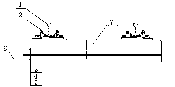
[0045] Such as figure 1 As shown, the method for adjusting the elevation of the ballast bed surface by 3D printing stacking forming of the present invention comprises the following steps:

[0046] (1) Establish a three-dimensional map of the elevation of the base surface; measure the elevation of the base surface in sections based on the slope adjustment diagram designed based on the line penetration survey and the tunnel section results, the poured base of the track construction drawing, and the layout of the prefabricated components. Establish a three-dimensional map mathematical model of the elevation of the base surface;

[0047] (2) Establish a three-dimensional digital model of prefabricated components; measure the flatness of the lower surface of each prefabricated component, and establish a three-dimensional mathematical model of the flatness of the lower surface...


PUM


Abstract

The invention discloses a 3D printing stack forming ballast bed elevation adjusting method. The 3D printing stack forming ballast bed elevation adjusting method comprises, according to a base poured according to a gradient and line adjusting drawing and a track construction drawing, which are designed according to line through measurement and tunnel section output, and a prefabricated part arrangement plan, sectionally performing base surface elevation measurement to establish a base surface elevation three-dimensional map mathematical model; measuring the flatness of the lower surface of every prefabricated part, and establishing a lower surface flatness three-dimensional mathematical model of every prefabricated part; based on design and practical mathematical models, producing 3D printing input files, and layer-by-layer printing materials onto the surface of the base or the prefabricated parts through numerical control 3D printing equipment. Between a base assembling layer and the prefabricated parts, elastic buffer layers different in thickness are arranged to adjust the elevation of a ballast bed to meet the requirements of tracks on directional, horizontal and height smoothness and meanwhile a prefabricated part adjusting surface can meet the requirement that the prefabricated parts can be directly assembled on the base. The 3D printing stack forming ballast bed elevationadjusting method is rapid in construction speed and high in precision and is a key technical breakthrough of green track manufacturing.

Description

technical field [0001] The invention relates to the technical field of rail transit engineering, including slab track construction for high-speed railways, national railways, urban railways or urban rail transit, and in particular to a method for adjusting the elevation of the track bed surface by 3D printing and stacking. Background technique [0002] Large-capacity, energy-saving, environmentally friendly, safe and fast rail transportation. The track is the foundation of the transportation equipment. The track directly bears the load of the train and guides the train to run. The track structure must have sufficient strength and stability. Track laying is one of the key links in the construction of rail transit projects. The start of track construction is a milestone node target for the track. The start of track laying marks that the construction of rail transit has achieved phased results. The various "points" of civil engineering in stations and sections will be Through t...

Claims


Application Information

Patent Timeline
Patent Type & Authority Applications(China)
IPC IPC(8): E01B29/00E01B1/00E01B19/00
CPCE01B29/00E01B1/002E01B19/003E01B2204/01E01B2204/06E01B2204/09
Inventor 廖环武陆健祖恺先石江飞吕迪凡黄家才陈秋斌莫镇艳
Owner GUANGXI SANWEI RAIL MANUFACTURING CO LTD
Why Eureka
Try Eureka