
Anchor cable supporting system with impact resistance

An anchor cable support and impact resistance technology, which is used in the installation of anchor rods, mining equipment, earthwork drilling, etc., can solve the problems of lack of anti-fall protection function and insufficient support of anchor cable support structure

Pending Publication Date: 2018-04-20
中天合创能源有限责任公司
View PDF7 Cites 2 Cited by
  • Summary
  • Abstract
  • Description
  • Claims
  • Application Information

AI Technical Summary

Problems solved by technology

[0003] The purpose of the present invention is to address the technical defects of the prior art and provide an anchor cable support system with impact resistance to solve the problem that the anchor cable support structure support in the prior art is not strong enough and does not have the function of anti-fall protection question

Method used


Image

  • Anchor cable supporting system with impact resistance
  • Anchor cable supporting system with impact resistance

Examples


Embodiment 1

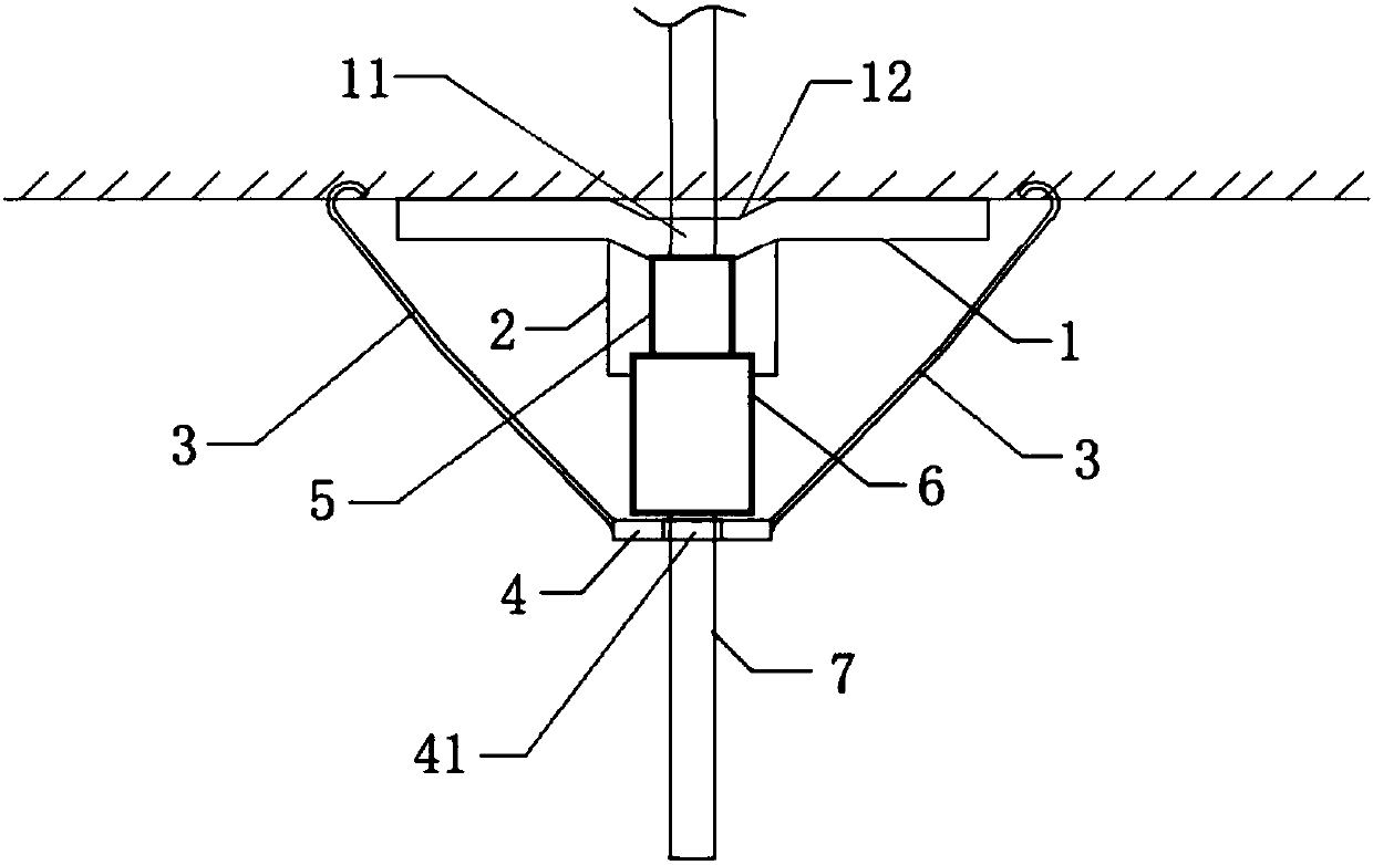
[0021] An anchor cable support system with impact resistance, comprising pressure relief tray 1, pressure pipe protective cover 2, anti-drop hook 3, anti-fall ring 4, pressure pipe 5, lock 6, anchor cable 7, the The pressure relief tray 1 is rectangular, and the central position of the pressure relief tray 1 has a recessed part 12, and the center position of the recessed part 12 has a first anchor cable hole 11, and the lower end of the recessed part 12 is fixedly connected with a pressure relief pipe protection Cover 2, the pressure-releasing tube protective cover 2 is cylindrical, the pressure-releasing tube 5 is sleeved in the pressure-releasing tube protective cover 2, and the lower end of the pressure-relieving tube 5 is connected with a The lockset 6 with limiting effect, the anti-fall ring 4 is located below the lockset 6, the center of the anti-fall ring 4 has a second anchor cable hole 41, one end of the anti-fall hook 3 is a hook body, and the other end is a hanging r...

Embodiment 2

[0029] An anchor cable support system with impact resistance, comprising pressure relief tray 1, pressure pipe protective cover 2, anti-drop hook 3, anti-fall ring 4, pressure pipe 5, lock 6, anchor cable 7, the The pressure relief tray 1 is rectangular, and the central position of the pressure relief tray 1 has a recessed part 12, and the central position of the recessed part 12 has a first anchor cable hole 11, and the lower end of the recessed part 12 is fixedly connected with a pressure relief pipe protection Cover 2, the pressure-releasing tube protective cover 2 is cylindrical, the pressure-releasing tube 5 is sleeved in the pressure-releasing tube protective cover 2, and the lower end of the pressure-relieving tube 5 is connected with a The lockset 6 with limiting effect, the anti-fall ring 4 is located below the lockset 6, the center of the anti-fall ring 4 has a second anchor cable hole 41, one end of the anti-fall hook 3 is a hook body, and the other end is a hanging ...


PUM

PropertyMeasurementUnit
Tensile strength valueaaaaaaaaaa

Abstract

The invention provides an anchor cable supporting system with impact resistance. According to the technical scheme, an anchor cable penetrates through a pressure yielding tray, and a sunk part achieving the pressure yielding effect is arranged at the penetrating portion; meanwhile, a pressure yielding protective hood is arranged on the bottom face of the sunk part, a pressure yielding pipe is arranged in the sunk part, and a lock achieving the limiting effect is arranged at the bottom of the pressure yielding pipe; an annular object achieving an anti-fall protection effect is arranged below the lock and is hung at one end of the anti-fall hook, the other end of the anti-fall hook is hung on a rock body, and thus the anchor cable, the pressure yielding pipe, the lock and the like are all borne and protected by an anti-fall ring. Through the technological improvement, the anti-impact effect of the anchor cable in the vertical direction is achieved, and meanwhile, the anchor cable supporting system has an anti-fall protection function.

Description

technical field [0001] The invention relates to the technical field of support materials for underground engineering, in particular to an anchor cable support system with impact resistance. Background technique [0002] The anchor cable support technology is widely used in coal mine roadways or other underground engineering fields. This technology mainly applies prestress to the reinforced rock mass through anchor cables to limit excessive deformation of the rock mass and improve the stress of the surrounding rock mass in the roadway or other underground spaces. State, improve the self-supporting capacity of the surrounding rock mass, so as to maintain the stability of the surrounding rock. Anchor cable support technology is very important for underground engineering support, especially for coal mine roadways under strong mine pressure conditions such as rock burst, because the surrounding rock and support system of this type of roadway will experience high ground pressure a...

Claims


Application Information

Patent Timeline
IPC IPC(8): E21D21/00
CPCE21D21/0026E21D21/008E21D21/0086
Inventor 朱稳樑朱若军翁明月周剑陈云民刘志刚唐东旭
Owner 中天合创能源有限责任公司
Learn More