Emergency core cooling system for nuclear power plant

An emergency core and cooling system technology, applied in reactors, nuclear power generation, cooling devices, etc., can solve problems such as uneven flow distribution at injection points, leakage of penetrating parts, complex system configuration, etc., to eliminate the increase of penetrating parts and increase safety The effect of injecting flow rate and simplifying system configuration

Active Publication Date: 2018-04-20
CHINA NUCLEAR POWER TECH RES INST CO LTD +2
View PDF5 Cites 10 Cited by
  • Summary
  • Abstract
  • Description
  • Claims
  • Application Information

AI Technical Summary

Problems solved by technology

The safety injection system disclosed in this Chinese patent has the following problems: 1) Its high-pressure safety injection and low-pressure safety injection adopt parent control injection, that is, if figure 1 As shown, the injection pipelines at the outlet of the safety injection pumps are connected to each other, and each pump can inject to any injection point, and the number of injection pipelines increases. Secondly, the refueling water tank is set in the containment, from figure 1 It can be seen that the connection between the system and the refueling water tank 207 needs to penetrate the containment vessel, and each pipeline penetrating the containment vessel must be provided with a containment vessel penetration piece, resulting in an increase in

Method used


Image

  • Emergency core cooling system for nuclear power plant
  • Emergency core cooling system for nuclear power plant

Examples


Embodiment 1

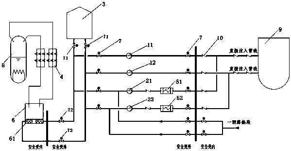
[0038] This embodiment is an emergency core cooling system of a nuclear power plant, and its system structure schematic diagram is as follows figure 2 As shown, compared with the prior art system, the improved emergency core cooling system still adopts safe injection methods under three pressure levels of high, medium and low, but this embodiment greatly simplifies the system configuration. Specifically, the nuclear power plant emergency core cooling system in this embodiment includes a high-pressure safety injection pump, a low-pressure safety injection pump, a safety injection water tank 3, an automatic pressure relief system (ADS) 4, a pressurizer 8, a pressure vessel 9 and a direct Injection pipeline, waste heat discharge heat exchanger 5 and containment suppression tank 6, wherein the automatic pressure relief system (ADS) 4, containment suppression tank 6, pressurizer 8, pressure vessel 9 and direct injection pipeline are set Inside the containment, the high-pressure sa...

Embodiment 2

[0052] Embodiment 2 is based on Embodiment 1 to further optimize the design of the low-pressure installation pump and high-pressure safety injection pump and the quantity and arrangement of waste heat discharge heat exchanger 5, but the low-pressure installation pump, high-pressure safety injection pump and waste heat The discharge heat exchanger 5 is not limited to the design of this embodiment.

[0053] In this embodiment, the first high-pressure safety injection pump 11, the second high-pressure safety injection pump 12, the first low-pressure safety injection pump 21, the second low-pressure safety injection pump 22, the safety injection water tank 3, the automatic pressure relief system 4, The connection relationship between the first waste heat discharge heat exchanger 5, the second waste heat discharge heat exchanger 5, the containment suppression pool 6, the pressurizer 8 and the pressure vessel 9 is as follows: figure 2 As shown, specifically, the low-pressure safety...


PUM


Abstract

The invention discloses an emergency core cooling system for a nuclear power plant. The system specifically comprises a high-pressure safety injection pump, a low-pressure safety injection pump, a safety water injection tank, an automatic pressure relief system, a pressure stabilizer, a direct injection pipeline, a waste heat removal heat exchanger, a pressure container and a containment pressuresuppression pool, wherein the automatic pressure relief system, the containment pressure suppression pool, the pressure stabilizer, the pressure container and the direct injection pipeline are arranged in a containment, and the high-pressure safety injection pump, the low-pressure safety injection pump, the safety water injection tank and the waste heat removal heat exchanger are arranged outsidethe containment. Compared with the prior art, the system provided by the system combines the low-pressure safety injection function and the waste heat removal function, so that system configuration issimplified, and economical efficiency is improved. The pressure suppression pool is arranged in the containment, and a containment pit is removed, so that the volume of the containment and the configuration of a recirculation filter are greatly reduced. The safety water injection tank is arranged out of the containment, the problems that the containment penetration pieces is increased, and pipeline arrangement is complex and the like caused by the arrangement of a refuelling water tank in the containment are eliminated.

Description

technical field [0001] The invention relates to the technical field of nuclear power plant equipment, in particular to an emergency core cooling system of a nuclear power plant. Background technique [0002] The safety injection system is also called the emergency core cooling system, which is mainly used to ensure the emergency safety shutdown of the reactor and discharge the residual heat of the core for a long time under various hypothetical accident conditions. At present, most large pressurized water reactor nuclear power plants are equipped with a safety injection system to perform emergency core cooling under accident conditions and maintain the water loading of the primary circuit. In order to achieve the above functions, the safety injection system must be injected at different pressure levels according to the pressure drop of the primary circuit system during the accident. [0003] The security injection system in the prior art consists of three subsystems: [00...

Claims


Application Information

Patent Timeline
IPC IPC(8): G21C15/18
CPCG21C15/18Y02E30/30
Inventor 张琪谭璞张守杰张立德帅剑云
Owner CHINA NUCLEAR POWER TECH RES INST CO LTD
Why Eureka
Try Eureka