Passive series-fed electronically steered dielectric travelling wave array

An array and waveguide technology, applied in the field of series-fed phased array antennas, can solve problems such as bandwidth constraints and frequency sensitivity of series-fed arrays, and achieve cost-effective results

Active Publication Date: 2018-04-20
AMI RES & DEV
View PDF13 Cites 7 Cited by
  • Summary
  • Abstract
  • Description
  • Claims
  • Application Information

AI Technical Summary

Problems solved by technology

[0007] However, series-fed arrays are usually frequency sensitive and thus lead to bandwidth constraints

Method used


Image

  • Passive series-fed electronically steered dielectric travelling wave array
  • Passive series-fed electronically steered dielectric travelling wave array
  • Passive series-fed electronically steered dielectric travelling wave array

Examples


Embodiment Construction

[0051] 1 Introduction

[0052] In microwave phased array antennas, it is desirable to simplify the design and fabrication of the work-splitting network. In such components, individual phase control elements are placed in series between each radiating element. In this cascade configuration, the transmission line (which can be a waveguide or any other transverse electromagnetic mode (TEM) line) contains all the antenna element tappoints that control power division and sidelobe levels as well as control the scan angle of the array the phase shifter. This arrangement provides a savings in required electronic circuitry compared to a parallel feed structure which would normally require more bi-directional power splitters to achieve the same function.

[0053] By way of introduction only, this simplification can be provided by changing the wave propagation velocity of the transmission line to perform a phase shift function, thereby inducing a change in electrical length between ele...


PUM


Abstract

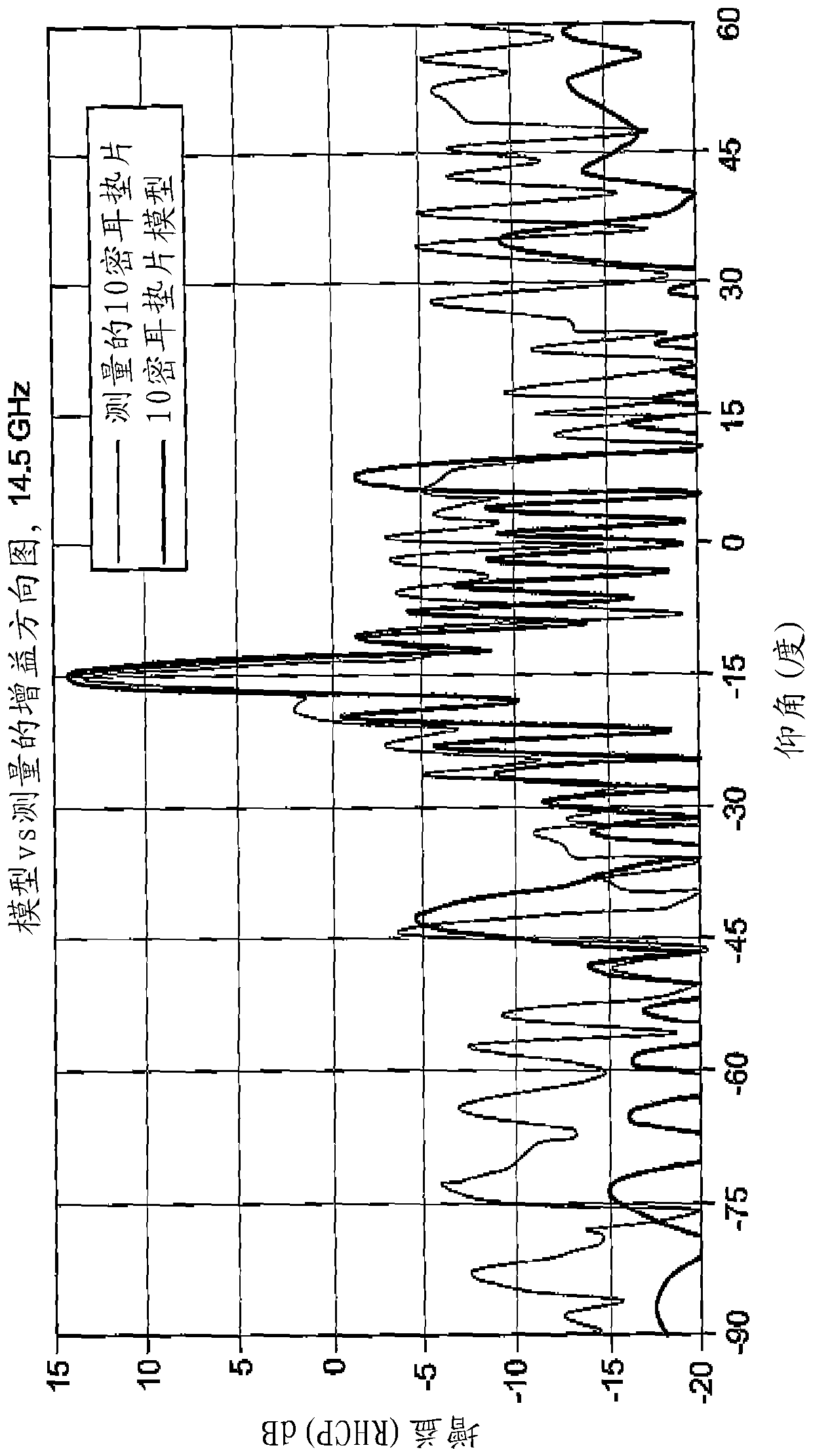
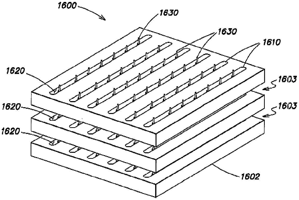
The invention discloses a passive series-fed electronically steered dielectric travelling wave array. According to the invention, a low cost passive electronic scanning array based on a Dielectric Traveling Wave Array (DTWA) technology that uses micro-actuated control of a waveguide transmission medium feeding the array elements to steer the array beam. Array gain is achieved by coherently combining element outputs with very low loss, weighted waveguide directional couplers. By modifying the propagation delay of the dielectric-filled waveguide through the introduction of a variable air gap, the radiated phase of the coupled patch array elements is changed, steering the beam accordingly. Since the circuitry is passive and bi-directional, the same antenna array can be used on receive or transmit unlike an active phased array that requires transmit / receiver switching. The design has been validated at Ku-Band through brassboard testing and is scalable with simulation at Ka-Band, steering the beam over a Field of Regard (FoR) of + / - 50o with nearly uniform gain. The approach provides phase control without active components at each individual array element, which significantly reduces the cost of a phased array by at least an order of magnitude.

Description

[0001] Cross References to Related Applications [0002] This application may relate to U.S. Patent Application Serial Nos. US 13 / 372,122, US 13 / 372,117, US 13 / 357,448, and US 14 / 193,072, as well as patent applications including WO 2012 / 109652, US 2012 / 0274528, US2012 / 0206310, and US2012 / 0744375. Published patent application documents. technical field [0003] This patent relates to series-fed phased array antennas, and in particular to coupler(s) disposed between the radiating antenna elements of the array and waveguide(s) with adjustable wave propagation constants. Background technique [0004] Military, commercial and consumer users demand ever-increasing data bandwidth, both inside and outside terrestrial data networks. Bandwidth demands are doubling every two (2) to three (3) years, and satellites expected to meet these demands are launched to provide data services with economies of scale. While sufficient satellite bandwidth is available at this time, existing satell...

Claims


Application Information

Patent Timeline
Patent Type & Authority Applications(China)
IPC IPC(8): H01Q3/26H01Q3/32H01Q3/36H01Q3/44H01Q5/35H01Q9/04H01Q15/16H01Q21/00H01Q21/06
CPCH01Q3/2694H01Q3/32H01Q3/36H01Q3/443H01Q9/0435H01Q15/16H01Q21/0037H01Q21/0068H01Q21/065H01Q5/35
Inventor J.T.阿波斯托罗斯W.穆约斯B.麦克马洪B.莫伦P.吉尔
Owner AMI RES & DEV
Why Eureka
Try Eureka