A fast chip removal polishing pad

A polishing pad and fast technology, applied in the direction of grinding tools, etc., can solve the problems of scrap scratches and difficult discharge of scrap, and achieve the effect of reducing resistance, good drag reduction effect, and good chip removal effect.

Active Publication Date: 2020-04-07
NANJING UNIV OF AERONAUTICS & ASTRONAUTICS +1
View PDF8 Cites 2 Cited by
  • Summary
  • Abstract
  • Description
  • Claims
  • Application Information

AI Technical Summary

Problems solved by technology

[0008] In order to solve the defect in the prior art that the waste chips generated by polishing are difficult to discharge in the processing area, resulting in the waste chips constantly scratching the surface of the workpiece, the present invention provides a fast chip removal polishing pad, because the groove accelerates the flow of the polishing liquid, The polishing liquid on the surface of the polishing pad is updated more quickly, the chemical effect of the polishing liquid on the workpiece is more sufficient, and the material removal rate is stable

Method used


Image

  • A fast chip removal polishing pad
  • A fast chip removal polishing pad
  • A fast chip removal polishing pad

Examples


Embodiment Construction

[0031] The present invention will be further described below in conjunction with the accompanying drawings and embodiments.

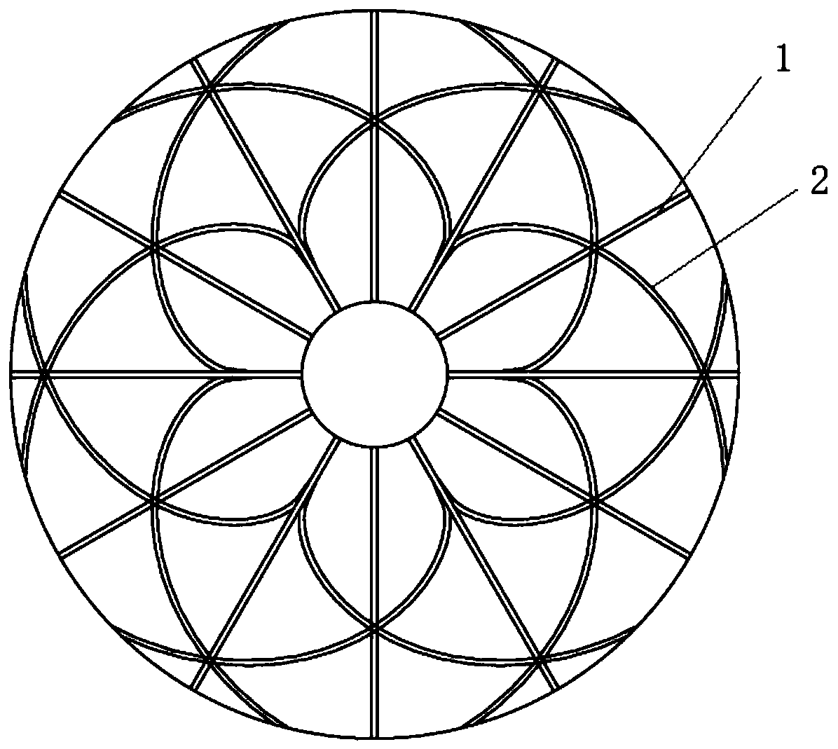
[0032] Such as figure 1 As shown, the present embodiment provides a fast chip removal polishing pad, which includes a main chip removal groove 1 and a secondary chip removal groove 2, the main chip removal groove 1 is composed of 10-14 divergent grooves, All divergent grooves are centered on the center of the polishing pad and distributed on the surface of the polishing pad at an equal angle;

[0033] The auxiliary chip removal groove 2 is composed of 10-14 spiral grooves, and each spiral groove is centered on the center of the polishing pad and distributed equiangularly on the surface of the polishing pad.

[0034] The present invention utilizes the centrifugal force generated by the rotation during the polishing process to the greatest extent through the divergent main chip removal groove, so that the waste chips generated during processing leave the...


PUM


Abstract

The invention discloses a polishing pad capable of quickly removing chips. The polishing pad comprises a main chip removing groove and a secondary chip removing groove; the main chip removing groove is a scattered groove; the section of the groove is an inverted trapezoid; the groove forms a slightly downward slope from a starting point to an ending point; the secondary chip removing groove is a spiral groove; the section of the groove is a rectangle; and the shape of the groove meets a certain mathematical relation. The polishing pad can realize quick discharge of machining waste chips, reduces influence on the machining process by the waste chips, improves the workpiece surface quality, and reduces the damage.

Description

technical field [0001] The invention relates to a tool for precision machining, in particular to a polishing pad for chemical mechanical polishing, in particular to a fast chip removal polishing pad. Background technique [0002] Chemical mechanical polishing (CMP) technology, as the only process method that can achieve global planarization, is widely used in ultra-precision processing of integrated circuits, computer magnetic heads, hard disks, and optics. [0003] In the CMP process, the material removal from the processed surface is mainly realized through the interaction between the polishing liquid and the polishing pad. Among them, the polishing liquid plays the role of lubricating the processing surface, softening and corroding the processing surface, absorbing the heat of chemical reaction and taking away the processing waste; while the polishing pad can transfer mechanical load, maintain the polishing environment, and mechanically remove and transport the workpiece ...

Claims


Application Information

Patent Timeline
Patent Type & Authority Patents(China)
IPC IPC(8): B24B37/26
CPCB24B37/26
Inventor 李军黄俊阳王健杰朱永伟左敦稳张羽驰明舜
Owner NANJING UNIV OF AERONAUTICS & ASTRONAUTICS
Why Eureka
Try Eureka