
Efficient, movable and integrated sewage treatment device

A kind of sewage treatment equipment, high-efficiency technology, applied in water/sewage treatment, water/sewage multi-stage treatment, water/sludge/sewage treatment, etc., can solve the problems of large footprint, long treatment time, long construction period, etc. , to achieve good impact load resistance, short processing time and good mud discharge effect

Pending Publication Date: 2018-04-24
ANHUI SHUNYU WATER AFFAIRS CO LTD
View PDF5 Cites 0 Cited by
  • Summary
  • Abstract
  • Description
  • Claims
  • Application Information

AI Technical Summary

Problems solved by technology

At present, my country's cities have established a relatively complete centralized sewage treatment system. In areas where pollution sources such as rural domestic sewage, small and medium-sized enterprises wastewater, tourist landscape sewage, and highway service area sewage are scattered, sewage treatment equipment is gradually being established, but ordinary sewage When the treatment equipment is actually used in areas with scattered pollution sources, there are the following problems: no anti-shock load performance, long treatment time, poor treatment effect, large floor area, inconvenient post-management, long construction period, and effluent water quality unstable
At the same time, the sludge discharge system of ordinary sewage treatment equipment has the disadvantages of high energy consumption and poor sludge discharge effect of the movable self-priming sludge discharge device
Due to the existence of the above problems, the sludge discharge device of ordinary sewage treatment equipment cannot meet the actual needs of emergency treatment of water bodies, point source control of black and odorous water bodies, advanced treatment of municipal sewage, and upgrading of tail water in sewage plants.

Method used


Image

  • Efficient, movable and integrated sewage treatment device
  • Efficient, movable and integrated sewage treatment device
  • Efficient, movable and integrated sewage treatment device

Examples


Embodiment Construction

[0016] The following will clearly and completely describe the technical solutions in the embodiments of the present invention with reference to the accompanying drawings in the embodiments of the present invention. Obviously, the described embodiments are only some, not all, embodiments of the present invention. Based on the embodiments of the present invention, all other embodiments obtained by persons of ordinary skill in the art without making creative efforts belong to the protection scope of the invention.

[0017] The present invention will be further described in detail below in conjunction with the schematic flow chart and specific implementation methods.

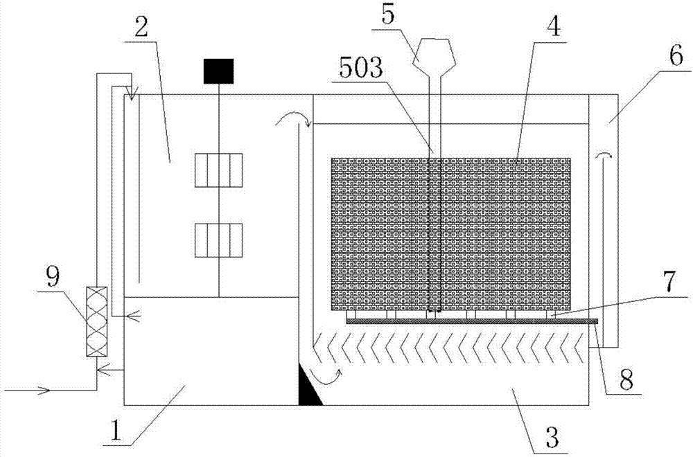
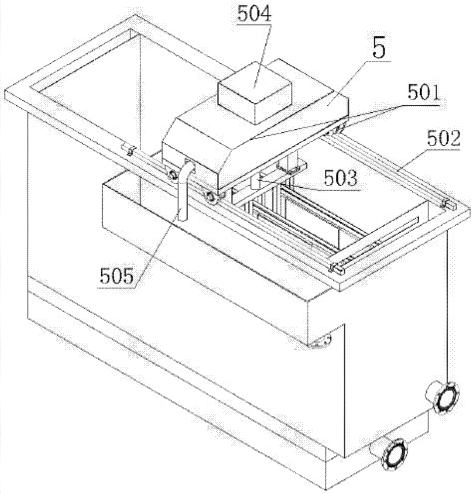
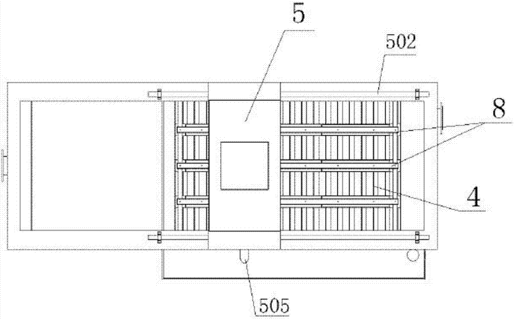
[0018] A high-efficiency mobile integrated sewage treatment equipment, which is characterized in that it includes an outer shell and an inner shell area inside the outer shell. The inner shell area sequentially includes a dosing area 1, a pretreatment area 2, a precipitation area 3, a filtration area 4, and a mud suc...


PUM


Abstract

The invention discloses an efficient, movable and integrated sewage treatment device which is characterized in that the device comprises a shell and a shell inner area in the shell, a chemical feedingarea, a pretreating area, a sedimentation area, a filtering area, a sludge absorption area and a water discharging weir area are sequentially arranged in the shell inner area, the chemical feeding area is connected with the pretreating area through a chemical feeding pipe and positioned above the pretreating area, the sedimentation area, the filtering area and the sludge absorption area are positioned on the right side or left side of the pretreating area, the sedimentation area is positioned above the filtering area, partition plates are arranged between the pretreating area and the sedimentation area and between the sedimentation area and the filtering area, and the water discharging weir area is positioned on the rear of the filtering area and the sedimentation area and connected withthe filtering area and the sedimentation area through water discharging main pipes. The device is high in impact-resistant load ability and stability, rapid in treatment, small in occupied area, easyto construct, low in energy consumption, good in sludge discharging effect and discharged water quality and suitable for popularization and application in sewage treatment of the areas with dispersedpollution sources.

Description

technical field [0001] The invention relates to the technical field of sewage treatment, in particular to a highly efficient mobile integrated sewage treatment equipment. Background technique [0002] With the development of the economy and the improvement of living standards, the people's requirements for environmental protection are getting higher and higher. At present, my country's cities have established a relatively complete centralized sewage treatment system. In areas where pollution sources such as rural domestic sewage, small and medium-sized enterprises wastewater, tourist landscape sewage, and highway service area sewage are scattered, sewage treatment equipment is gradually being established, but ordinary sewage When the treatment equipment is actually used in areas with scattered pollution sources, there are the following problems: no anti-shock load performance, long treatment time, poor treatment effect, large floor area, inconvenient post-management, long con...

Claims


Application Information

Patent Timeline
Patent Type & Authority Applications(China)
IPC IPC(8): C02F9/04
CPCC02F9/00C02F2001/007C02F1/00C02F1/001
Inventor 李辰潘军高静
Owner ANHUI SHUNYU WATER AFFAIRS CO LTD
Learn More