U-shaped flame reciprocating heating trolley-type heat treatment device and treatment method thereof

A trolley-shaped, U-shaped technology, used in heat treatment equipment, heat treatment furnaces, furnaces, etc., can solve the problems of unsatisfactory heat treatment process requirements, unfavorable flame propagation, poor thermal conductivity, etc. Dynamic heat load adjustment, the effect of ensuring quality and performance

Pending Publication Date: 2018-04-24
SINOSTEEL ANSHAN RES INST OF THERMO ENERGY CO LTD
View PDF10 Cites 2 Cited by
  • Summary
  • Abstract
  • Description
  • Claims
  • Application Information

AI Technical Summary

Problems solved by technology

[0006] 1) The furnace temperature is uneven, and the temperature difference of the processed workpiece is large, which seriously affects the performance of the heat-treated product
[0007] 2) The conduction and transmission of the temperature flow field cannot be effectively organized in the furnace, and the effective conversion between energy flows cannot be fully realized, so precise heat treatment processes cannot be realized and high energy consumption and low output
[0008] 3) The traditional pad iron has large heat storage, poor thermal conductivity, and short life, which is not conducive to flame propagation, resulting in a serious impact on the temperature black mark of heat-treated products
[0009] 4) The function of the furnace is single, and the various temperature systems of the heat treatment process cannot be used for multiple purposes in one furnace, which cannot meet the heat treatment process requirements of multi-functional and multi-variety ultra-thick plates and composite plates.
[0010] 5) The hardware function of the combustion system is missing, the software control thinking is rigid and aging, there is no accurate detection and control means, frequent under-burning and large temperature deviations, over-burning and burning of workpieces and shims, not only serious energy waste, but also bring Industrial pollution from waste products and waste residues

Method used


Image

  • U-shaped flame reciprocating heating trolley-type heat treatment device and treatment method thereof
  • U-shaped flame reciprocating heating trolley-type heat treatment device and treatment method thereof
  • U-shaped flame reciprocating heating trolley-type heat treatment device and treatment method thereof

Examples


Embodiment Construction

[0039] The specific embodiments of the present invention will be further described below in conjunction with the drawings:

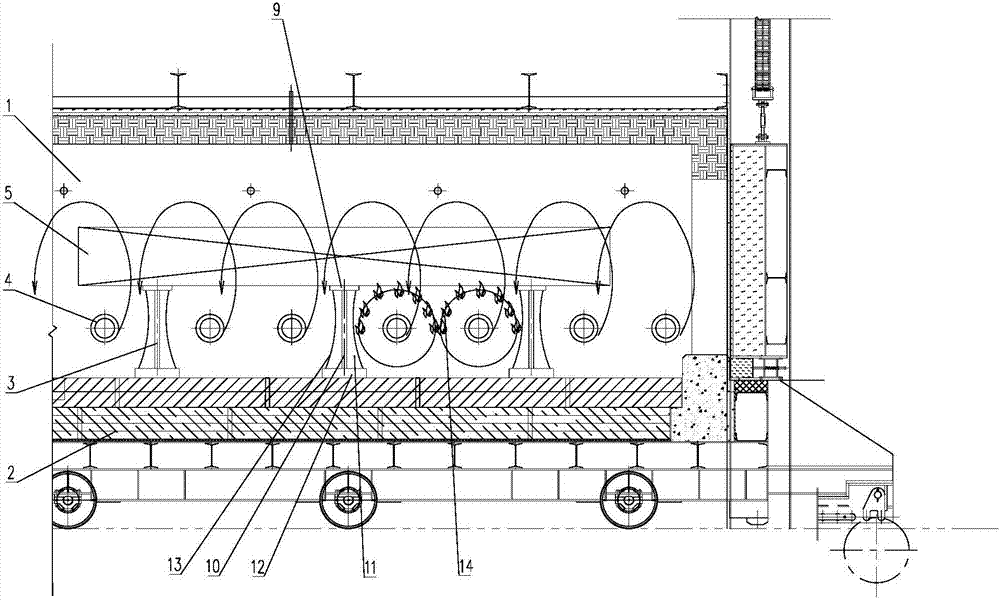
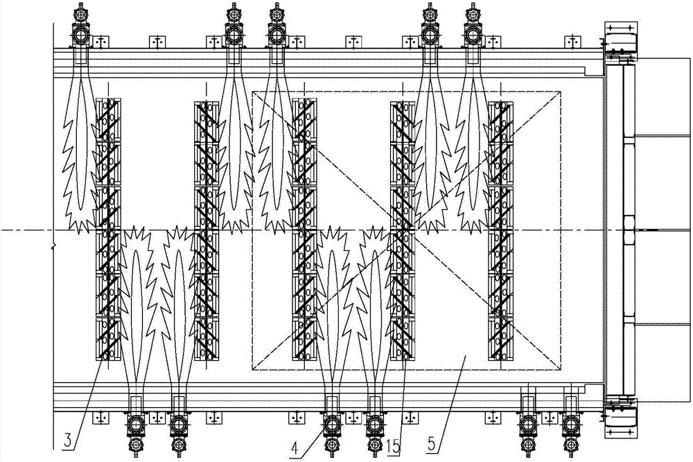
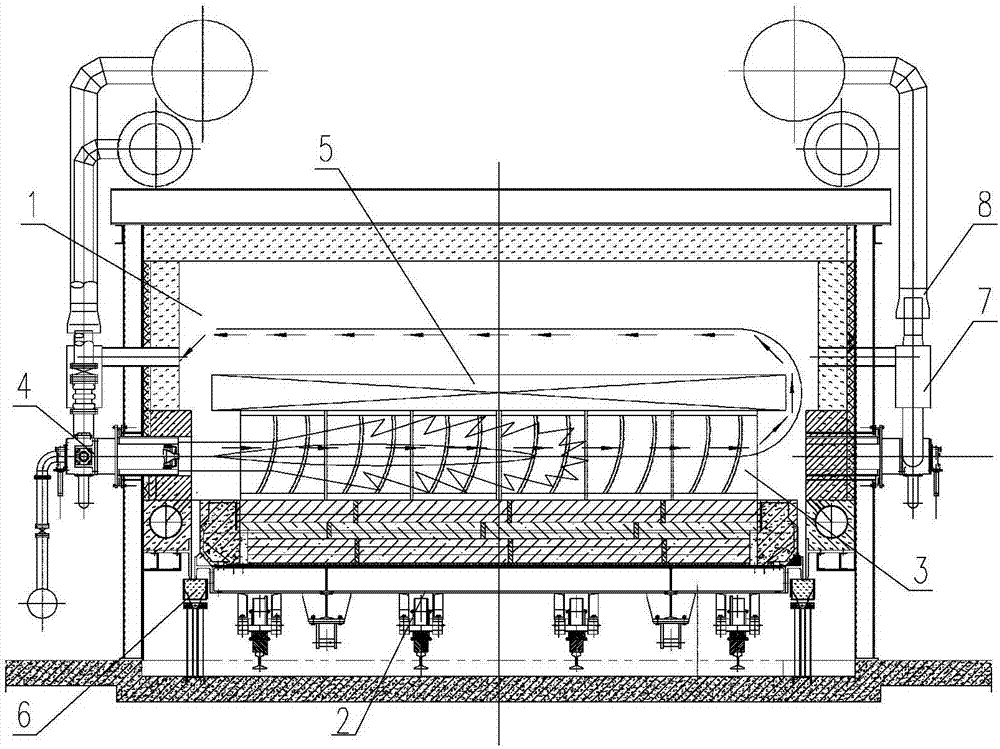
[0040] Such as figure 1 , figure 2 , image 3 As shown, a U-shaped flame reciprocating heating trolley-type heat treatment equipment includes a furnace body 1, a furnace car 2, a pad iron 3, a burner 4, a workpiece 5, a sealing system 6, an air supply system 7, and a smoke exhaust system 8. And its auxiliary loading and discharging positioning system, electric drive and instrument automation system and video transmission system. The burner 4 is connected to the air supply system 7 and the smoke exhaust system 8 through pipelines.

[0041] Multiple horns 3 are arranged in a row, and the multiple rows of horns 3 are placed parallel to each other on the furnace cart 2. The burners 4 are staggered and fixed on both sides of the furnace wall of the furnace body 1, and the burner 4 is located between the multiple rows of horns In the gap; the burner 4 and the hor...


PUM


Abstract

The invention relates to a heat treatment kiln device and heat treatment method for products such as a super thick plate, a composite plate and the like, in particular to a U-shaped flame reciprocating heating trolley-type heat treatment device and a treatment method thereof. A plurality of sizing blocks are arranged in a row, multiple rows of the sizing blocks are placed in parallel to each otheron a furnace vehicle, and burners are fixed in a staggered manner on the furnace walls on both sides of a furnace and located in gaps between the sizing blocks in multiple rows; the burners, the sizing blocks and workpieces carried on the sizing blocks constitute a U-shaped energy flow channel for energy flow transmission. Side wall burners in opposite arrangement and a simultaneous heating operation system for the traditional trolley-type furnace are changed, the U-shaped flame reciprocating heating trolley-type heat treatment device has the advantages of U-shaped flame unilateral heat supply, U-shaped flame unilateral alternately reversing heat supply, U-shaped flame bilateral reciprocally and flexibly converting heat supply, cyclically reversing heat supply, interval drawing combustionheat supply, and flexible implementation of interval drawing, pulse and reciprocating heating temperature systems. Requirements of different process temperature systems are met, and a sustainable development strategy of energy conservation, emission reduction and clean production is also met.

Description

Technical field [0001] The invention relates to heat treatment furnace equipment and heat treatment process methods for products such as ultra-thick plates, composite plates and the like, in particular to a trolley type heat treatment equipment and a treatment method for U-shaped flame reciprocating heating. Background technique [0002] At present, the domestic heat treatment technology for ultra-thick plates and composite plates is relatively backward. Imported roller-hearth continuous annealing furnaces are basically used for heat treatment. Although the performance of imported equipment and treatment processes is excellent, they are only suitable for heat treatment of thin plates, and the investment cost is large. , Maintenance, repair and operation costs are high; and for the heat treatment of ultra-thick plates and composite plates, it is impossible to use this roller-hearth continuous annealing furnace. [0003] In order to meet the performance requirements of ultra-thick pl...

Claims


Application Information

Patent Timeline
Patent Type & Authority Applications(China)
IPC IPC(8): C21D1/52C21D9/00
CPCC21D1/52C21D9/00
Inventor 毕仕辉宋国栋孙成龙张世煜孙守钰赵春竹李欢
Owner SINOSTEEL ANSHAN RES INST OF THERMO ENERGY CO LTD
Why Eureka
Try Eureka