A semi-floating gate storage device with u-shaped trench and its manufacturing method

A technology for storage devices and manufacturing methods, applied in semiconductor/solid-state device manufacturing, semiconductor devices, electric solid-state devices, etc., can solve the problems of half-floating gate potential fluctuations, affecting the charge retention time in the half-floating gate, and large device fluctuations. Achieve the effects of reducing leakage and potential fluctuations, prolonging the charge storage time, and small fluctuations in performance parameters

Active Publication Date: 2020-06-09
SHANGHAI INTEGRATED CIRCUIT RES & DEV CENT +1
View PDF4 Cites 0 Cited by
  • Summary
  • Abstract
  • Description
  • Claims
  • Application Information

AI Technical Summary

Problems solved by technology

However, in this type of semi-floating gate memory device structure, there is a parasitic MOSFET in the vertical direction of the channel on the side wall of the U-shaped trench; the MOSFET has a small threshold voltage Vt due to less channel doping and a small channel length, and has Strong short channel effect
This seriously affects the retention time of the charge in the half-floating gate, and will cause fluctuations in the potential of the half-floating gate, large fluctuations between devices, and large-scale integration.

Method used


Image

  • A semi-floating gate storage device with u-shaped trench and its manufacturing method
  • A semi-floating gate storage device with u-shaped trench and its manufacturing method
  • A semi-floating gate storage device with u-shaped trench and its manufacturing method

Examples


Embodiment Construction

[0038] The specific embodiment of the present invention will be further described in detail below in conjunction with the accompanying drawings.

[0039] It should be noted that, in the following specific embodiments, when describing the embodiments of the present invention in detail, in order to clearly show the structure of the present invention for the convenience of description, the structures in the drawings are not drawn according to the general scale, and are drawn Partial magnification, deformation and simplification are included, therefore, it should be avoided to be interpreted as a limitation of the present invention.

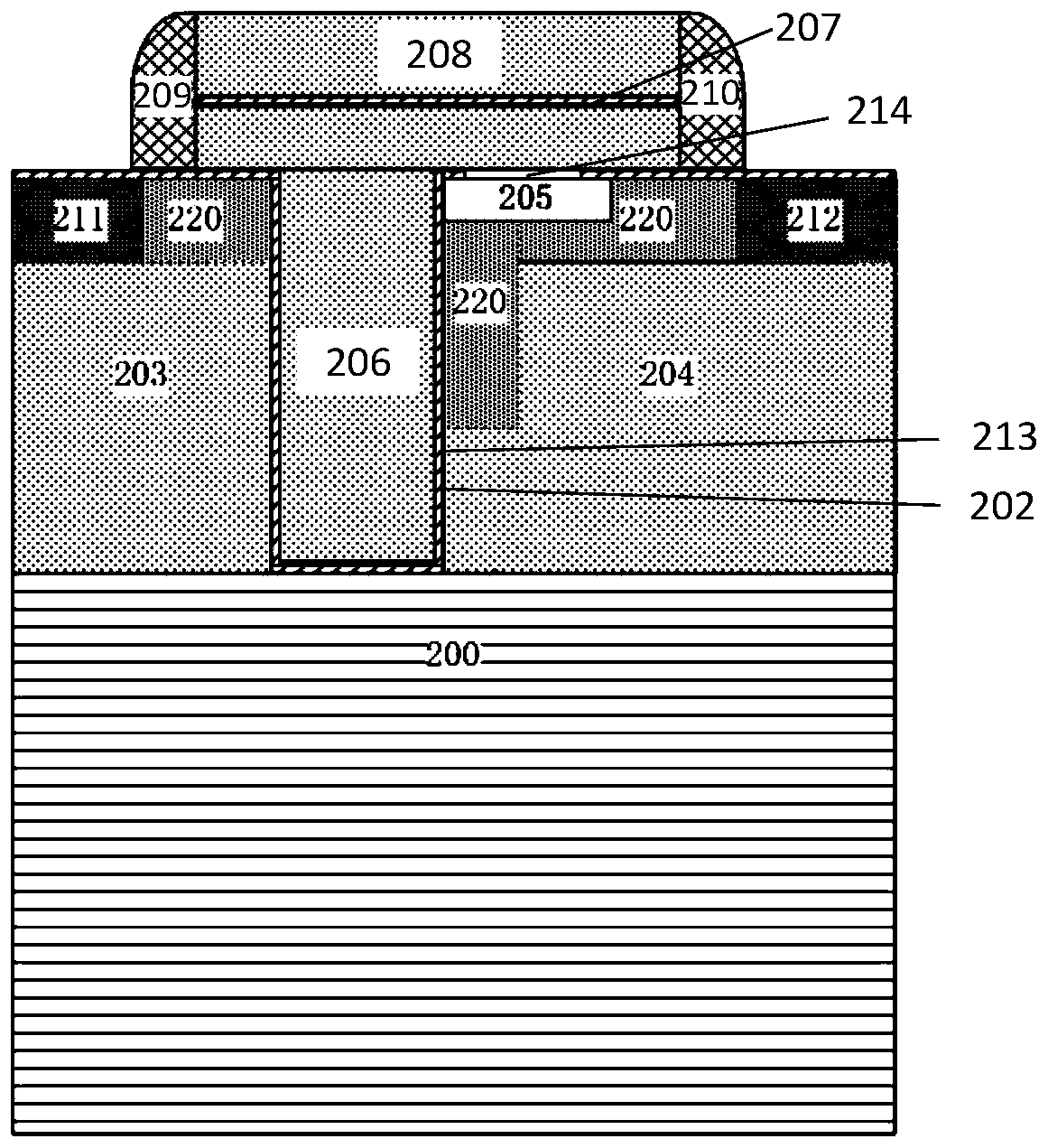
[0040] In the following specific embodiments of the present invention, please refer to figure 2 , figure 2 It is a schematic structural diagram of a semi-floating gate storage device with a U-shaped trench according to a preferred embodiment of the present invention. Such as figure 2 As shown, a semi-floating gate storage device with a U-shaped...


PUM

PropertyMeasurementUnit
thicknessaaaaaaaaaa

Abstract

The invention discloses a semi-floating gate storage device with a U-shaped trench and a manufacturing method thereof. After the threshold voltage Vt implantation of the U-shaped trench is completed, a large-angle implantation step is added, so that the The sidewall of the U-shaped trench forms a heavily doped region, which not only increases the threshold voltage of the parasitic MOSFET on the sidewall of the U-shaped trench, reduces the leakage and potential fluctuation of the half-floating gate, but also further enhances the charging current of the TFET to the half-floating gate. and shorten the writing time; the invention can increase the access speed, prolong the charge storage time of the half-floating gate, and at the same time, the performance parameter fluctuation between devices is small, and is suitable for large-scale integration.

Description

technical field [0001] The present invention relates to the technical field of semiconductor storage devices, and more particularly, to a semi-floating gate storage device with a U-shaped trench and a manufacturing method thereof. Background technique [0002] At present, semiconductor memory devices have been widely used in various electronic products. Among them, different application fields have different requirements on the structure, performance and density of semiconductor memory devices. For example, static random access memory (SRAM) has high random access speed and low integration density, while standard dynamic random access memory (DRAM) has high density and medium random access speed. [0003] As a new type of memory device, the semi-floating gate device can be applied to different integrated circuits. Semi-floating gate memory can replace a part of static random access memory (SRAM). The SRAM unit area composed of semi-floating gate transistors is smaller, and...

Claims


Application Information

Patent Timeline
Patent Type & Authority Patents(China)
IPC IPC(8): H01L27/102H01L21/8229
CPCH01L27/1022H10B99/00
Inventor 师沛
Owner SHANGHAI INTEGRATED CIRCUIT RES & DEV CENT
Why Eureka
Try Eureka