Improving method and structure of water release gate submerged orifice plane emergency gate

A technology of accident gate and sluice gate, which is applied in hydraulic engineering, marine engineering, coastline protection, etc., can solve problems such as poor hydraulic conditions, large thickness of parapet and gate, and cavitation, so as to ensure water-stop effect and structural safety. The effect of saving metal structure investment and saving civil construction investment

Pending Publication Date: 2018-04-27
CHINA POWER CONSRTUCTION GRP GUIYANG SURVEY & DESIGN INST CO LTD
View PDF0 Cites 0 Cited by
  • Summary
  • Abstract
  • Description
  • Claims
  • Application Information

AI Technical Summary

Problems solved by technology

[0003] The purpose of the present invention is to provide an improved method and structure of a submerged hole plane accident gate of a sluice sluice to overcome the large thickness of the breast wall and the gate in the prior art, the need to add a counterweight when the accident gate is closed, the large door groove, and the water The mechanical conditions are not good, cavitation, cavitation and other phenomena are prone to occur, and when the hydraulic pressure is filled, the water flow has a long range, and it is easy to impact the arc-shaped working gate panel, which induces the lack of vibration of the arc-shaped working gate.

Method used


Image

  • Improving method and structure of water release gate submerged orifice plane emergency gate
  • Improving method and structure of water release gate submerged orifice plane emergency gate
  • Improving method and structure of water release gate submerged orifice plane emergency gate

Examples


Embodiment

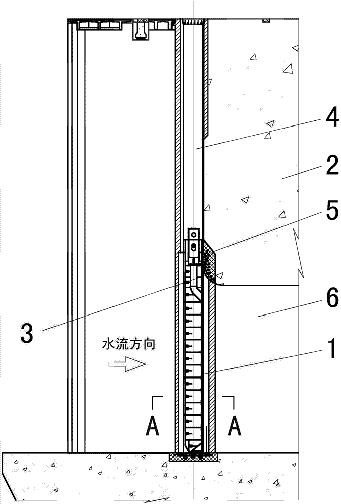
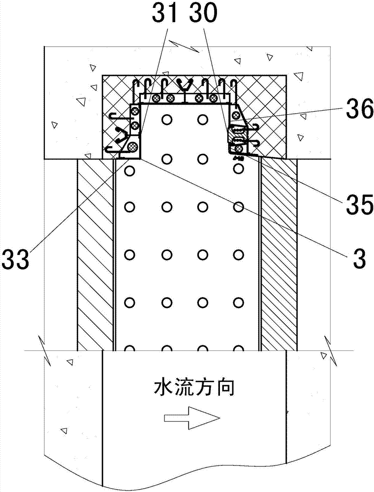
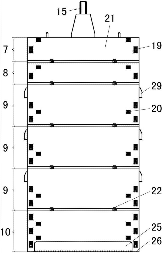
[0036] The submersible plane emergency gate of the discharge sluice in this example is set in front of the parapet 2, the lower edge of the parapet 2 is a bell mouth formed by the transition of the arc 3, the upstream of the plane emergency gate 1 is open, and the gate slot 4 of the plane emergency gate 1 It is an open upstream type II door slot, and the lintel 5 is arranged at the transition position of the arc 3 of the parapet 2 . The plane emergency gate 1 is formed by welding the top section door leaf 7, the second top section door leaf 8, the middle section door leaf 9 and the bottom section door leaf 10 to form an integral structure; the panel 21 of the plane emergency gate 1 is arranged on the upstream side, and the top water seal 11 and the side water seal 12 are arranged on the downstream side, and the bottom water seal 13 is arranged on the upstream side and the left and right sides along the water flow direction and is connected with the side water seal 12 .

[0037...


PUM


Abstract

The invention discloses an improving method and structure of a water release gate submerged orifice plane emergency gate. The water release gate submerged orifice plane emergency gate is moved to theupstream side of the outside of a water release gate breast wall from the inside of the water release gate breast wall, and therefore the water release gate breast wall does not need to be built to bethick, and investment cost of a water release gate is reduced; meanwhile, a panel on the upstream side of the plane emergency gate, a top beam and side columns are welded into a closed body, a top water seal and a side water seal of the plane emergency gate are arranged on the downstream side of the plane emergency gate and are connected with the bottom water seal to form a water seal device withthe closed periphery, water on the upper portion of the plane emergency gate forms downward water column pressure on the plane emergency gate, and therefore when the plane emergency gate is closed, abalance weight does not need to be additionally arranged, and the mounting program of the plane emergency gate is simplified. The defects that in the prior art, a breast wall and the gate are large in thickness, during door closing, the balance weight needs to be arranged, during water filing for flat pressing, the water flow range is far, an arc work gate panel is easily impacted, and vibrationof an arc work gate is induced.

Description

technical field [0001] The invention relates to an improvement method and structure of a submerged hole plane accident gate of a sluice gate, which belongs to the technical field of metal structures of water conservancy and hydropower projects. Background technique [0002] In water conservancy and hydropower projects, the submerged hole plane accident gate of the sluice generally adopts the upstream water stop fixed wheel support type or the downstream water stop slide block support type. The gate adopts the upstream water-stop fixed wheel support type. Since the gate slot is arranged in the breast wall of the sluice, the thickness of the breast wall is relatively large; this type of gate usually cannot overcome the closing resistance by relying on its own weight, and requires additional counterweight, civil engineering and metal structure investment. Larger; if the gate adopts the downstream water-stop slider support type, due to the large friction coefficient of the slide...

Claims


Application Information

Patent Timeline
IPC IPC(8): E02B7/20E02B7/54
CPCE02B7/20E02B7/54
Inventor 王兴恩徐祎杨清华高传彬李刚
Owner CHINA POWER CONSRTUCTION GRP GUIYANG SURVEY & DESIGN INST CO LTD
Why Eureka
Try Eureka