Iron bar automatic segmenting mechanism

An iron bar, automatic technology, applied in the direction of shearing device, device for cutting by nibbling action, attachment device of shearing machine, etc. Use and other issues to achieve a reasonable effect of structural design

Active Publication Date: 2018-05-01
ZHEJIANG ZHUOYI TEXTILE
View PDF5 Cites 7 Cited by
  • Summary
  • Abstract
  • Description
  • Claims
  • Application Information

AI Technical Summary

Problems solved by technology

Strip profiles mainly include metal iron bars. Iron bars can be composed of various stress components according to different structures, and can also be used as connectors between components. Iron bars are widely used in various building structures and engineering structures. Such as beams, bridges, transmission towers, lifting and transportation machinery, ships, industrial furnaces, reaction towers, container racks and warehouse shelves, etc., in the production and processing of iron bars, the iron bars need to be separated one by one according to the needs of the subsequent process. The section is cut, so that the iron bars with longer sizes can be cut evenly and efficiently, so that the iron bars cut into smaller sizes can be used normally in the subsequent process. The existing iron bars are in the process of cutting Mainly rely on workers to hold iron bars and use cutting equipment to cut into sections. The efficiency of iron bar cutting is low, and because the iron bars are cut manually, the quality of iron bars is poor, making it difficult to efficiently and accurately cut iron bars. According to the needs, the existing iron bar cutting mechanism is difficult to realize the automatic cutting of the iron bar. During the whole cutting process of the iron bar, workers need to manually load and unload the material. The work intensity of the workers is relatively high. The degree of automation of cutting is low, it is difficult to meet the needs of cutting large quantities of iron bars, and cannot meet the needs of processing and use

Method used


Image

  • Iron bar automatic segmenting mechanism
  • Iron bar automatic segmenting mechanism
  • Iron bar automatic segmenting mechanism

Examples


Embodiment Construction

[0015] In order to further describe the present invention, a specific implementation of an automatic iron bar cutting mechanism will be further described below in conjunction with the accompanying drawings. The following examples are explanations of the present invention and the present invention is not limited to the following examples.

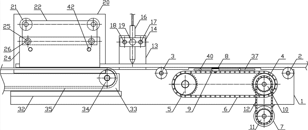
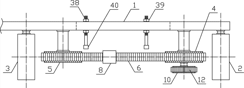
[0016] Such as figure 1As shown, an automatic section-cutting mechanism for iron bars of the present invention comprises a fixed bracket 1, a feeding mechanism, a material cutting mechanism and a fixed pushing mechanism, and the feeding mechanism, the cutting mechanism and the fixed pushing mechanism are fixedly arranged in a fixed position successively along the horizontal direction. On one side of bracket 1, the feeding mechanism includes feeding roller 2, guide roller 3, main feeding sprocket 4, auxiliary feeding sprocket 5, feeding chain 6, feeding motor 7 and feeding electromagnet 8, feeding roller 2 and feeding guide Roller 3 rotates h...


PUM


Abstract

The invention discloses an iron bar automatic segmenting mechanism, and belongs to the field of metal material processing mechanical equipment. The iron bar automatic segmenting mechanism includes a material-carrying mechanism, a material-cutting mechanism and a fixing material-pushing mechanism which are sequentially and fixedly arranged at one side of a fixing support in the horizontal direction, and a material-carrying chain which is winded is horizontally arranged between a main material-carrying chain and a secondary material-carrying chain; a material-carrying electromagnet is fixedly arranged at the outer side of the material-carrying guiding plate, a reciprocating material-cutting plate is slidably arranged at a material-cutting guiding rod in the horizontal direction, and a cutting handpiece is slidably arranged at the reciprocating material-cutting plate in the vertical direction; and a horizontal-pushing guiding rod is separately and horizontally fixed to two sides below a horizontal-pushing connecting plate, a fixing guiding plate and a moving guiding plate are separately and vertically arranged at two sides of the horizontal-pushing guiding rod, and the material-transporting mechanism is horizontally and fixedly arranged at the upper side of a material-transporting supporting plate. According to the iron bar automatic segmenting mechanism, the structural design isreasonable, iron bars can be transferred horizontally, stably, accurately and intermittently according to needed length, the iron bars can be clamped and cut and automatic feeding can be realized, andthe need for machining using can be met.

Description

technical field [0001] The invention belongs to the field of metal material processing machinery and equipment, and in particular relates to an automatic section cutting mechanism for iron bars, which is mainly used in the field of automatic cutting and processing of iron bars. Background technique [0002] Metal material refers to the general designation of metal elements or materials with metal characteristics mainly composed of metal elements, including pure metals, alloys, metal material compounds and special metal materials. Metal materials are mainly used in the form of profiles. Profiles are Iron or steel and materials with certain strength and toughness (such as plastic, aluminum, glass fiber, etc.) are objects with certain geometric shapes made by rolling, extrusion, casting and other processes. Profiles are widely used. According to the size and specifications of profiles, profiles can be used in industrial construction and metal structure fields, and can also be u...

Claims


Application Information

Patent Timeline
Patent Type & Authority Applications(China)
IPC IPC(8): B23D27/00B23D33/02
CPCB23D27/00B23D33/02
Inventor 赵锋朱辉夏忠
Owner ZHEJIANG ZHUOYI TEXTILE
Why Eureka
Try Eureka