
Calibration method of connecting rod parameters of industrial robot based on end-point plane constraint

An industrial robot, plane constraint technology, applied in manipulators, manufacturing tools, etc., can solve the problems of low degree of automation, low operability, low precision, etc., to reduce production costs, avoid low absolute positioning accuracy, kinematic model precise effect

Active Publication Date: 2018-05-01
HUAZHONG UNIV OF SCI & TECH
View PDF6 Cites 21 Cited by
  • Summary
  • Abstract
  • Description
  • Claims
  • Application Information

AI Technical Summary

Problems solved by technology

[0005] In view of the above defects or improvement needs of the prior art, the present invention provides a method for calibrating the parameters of the connecting rod of an industrial robot based on the plane constraints of the end points, which performs plane constraints on the end points to establish an error identification model of the connecting rod parameters of the industrial robot, And through the laser displacement sensor installed at the end of the industrial robot, the position information of the end point of the industrial robot under different positions and attitudes is obtained, and then the error of the connecting rod parameters of the industrial robot is identified, thereby solving the problem of low precision and automation of the existing calibration methods. It has the characteristics of simple operation, high calibration efficiency and strong practicability.

Method used


Image

  • Calibration method of connecting rod parameters of industrial robot based on end-point plane constraint
  • Calibration method of connecting rod parameters of industrial robot based on end-point plane constraint
  • Calibration method of connecting rod parameters of industrial robot based on end-point plane constraint

Examples


specific Embodiment

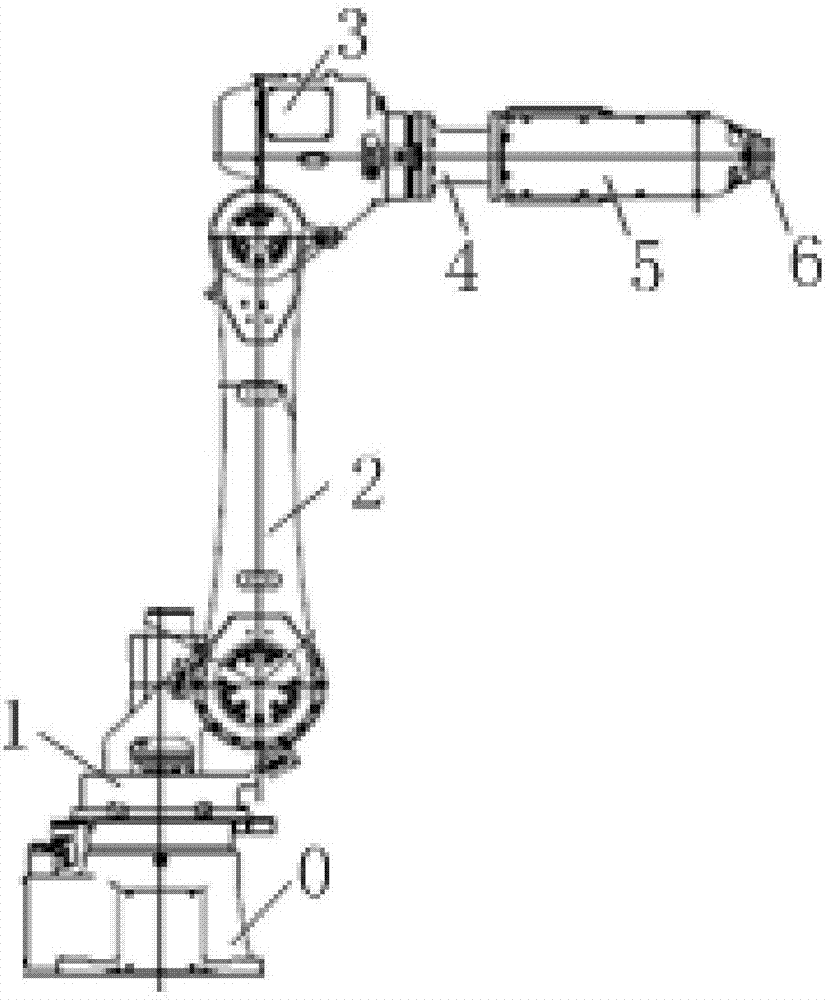
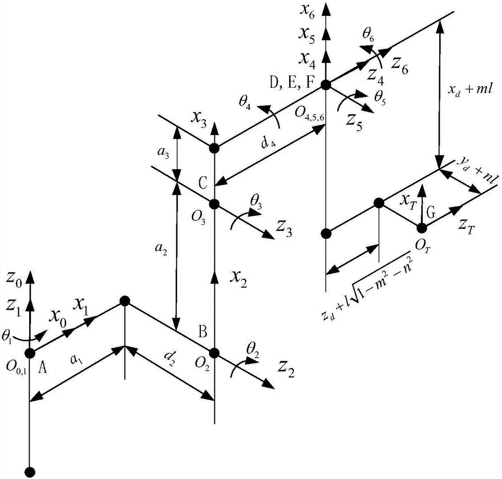
[0086] This embodiment takes Huazhong CNC 6012 industrial robot as an example, and its configuration is as follows figure 2 As shown, the Huazhong CNC 6012 industrial robot is an articulated robot, which consists of 6 revolving joints ( image 3 The points A, B, C, D, E, F shown) and 6 connecting rods ( figure 2 The 0-6 are connecting rod 0, connecting rod one, connecting rod two, connecting rod three, connecting rod four, connecting rod five, connecting rod six, connecting rod one to connecting rod six correspond image 3 The line segments AB, BC, CD, DE, EF, FG), the base is fixed and called link 0, the first joint connects the base and the first link, and the second joint connects the first link and the second The connecting rod, and so on, the tool is fixed to the connecting rod 6, and its connecting rod parameter calibration includes the following steps:

[0087] Step 1): According to the structural characteristics of the Huazhong CNC 6012 industrial robot and the DH method,...


PUM


Abstract

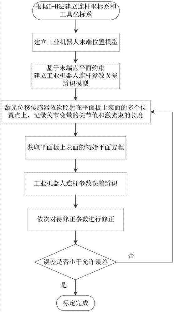
The invention belongs to the field of calibration of connecting rod parameters of an industrial robot, in particular to a calibration method of the connecting rod parameters of the industrial robot based on end-point plane constraint. The calibration method comprises the following steps: (1) establishing a connecting rod coordinate system and a tool coordinate system of the industrial robot, and thus obtaining the end position coordinate of the industrial robot; (2) conducting plane constraint for an end point, and establishing an error identification model of the connecting rod parameters ofthe industrial robot; (3) transforming the postures of the industrial robot, recording the joint values of joint variables and the length of a laser beam, and calculating the initial parameter of a plane equation according to the position coordinates of the first three poses; (4) conducting error identification for the connecting rod parameters of the industrial robot; and (5) correcting parameters to be corrected in order, and verifying the precision of the corrected industrial robot. The calibration method can conduct calibration in the larger working space of the industrial robot, can realize fully automatic calibration, and has high calibration precision and low cost.

Description

Technical field [0001] The invention belongs to the field of the parameter calibration of the connecting rod of an industrial robot, and more specifically relates to a method for calibrating the connecting rod parameter of an industrial robot based on the plane constraint of an end point. Background technique [0002] Robot errors can be divided into two categories: one is geometric parameter errors, which usually refer to errors in which the theoretical and actual values ​​of robot kinematic parameters are inconsistent due to processing, assembly or wear. The other is the non-geometric parameter error, which is caused by the flexibility of the robot transmission system and environmental factors. Its parameters include the stiffness of the joint servo, the stiffness of the connecting rod, the gear gap, and the friction. These errors will result in low pose accuracy at the end of the robot, which cannot meet the high precision requirements of modern industrial production. [0003] ...

Claims


Application Information

Patent Timeline
IPC IPC(8): B25J19/00
Inventor 宋宝郭艺璇唐小琦周向东熊烁徐意尹超唐玉儒王昌杰谢远龙
Owner HUAZHONG UNIV OF SCI & TECH
Learn More