Modular sewage treatment system

A sewage treatment system, modular technology, applied in the direction of oxidized water/sewage treatment, water/sewage multi-stage treatment, water/sludge/sewage treatment, etc., can solve ground digging maintenance, production inconvenience, underground pipeline blockage, etc. problems, to achieve the effect of increasing flow rate, facilitating cleaning operation and promoting reaction

Inactive Publication Date: 2018-05-01
四川宇科思通环保科技有限公司
View PDF0 Cites 1 Cited by
  • Summary
  • Abstract
  • Description
  • Claims
  • Application Information

AI Technical Summary

Problems solved by technology

[0003] The technical problem to be solved by the present invention is that if the sewage contains a lot of silt, silt or large particle suspended matter, if it is directly discharged through the underground pipeline, it will easily cause the underground pipeline to be blocked, and the staff will need to dig the ground for maintenance. Inconvenience to production, the purpose is to provide a modular sewage treatment system, and the sewage treatment equipment is installed between the outlet of the factory drainage equipment and the underground pipeline, and the preliminary treatment of the sewage can effectively prevent the blockage of the underground pipeline

Method used


Image

  • Modular sewage treatment system
  • Modular sewage treatment system

Examples


Embodiment 1

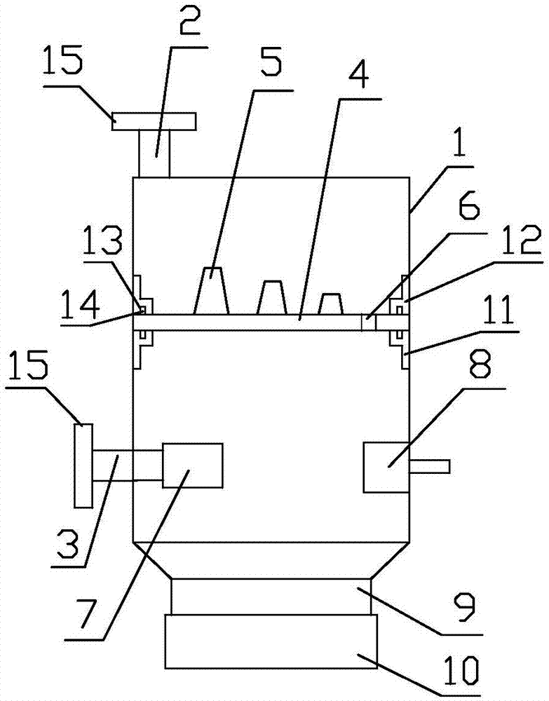
[0031] Such as figure 1 with figure 2 As shown, the modular sewage treatment system of the present invention includes a cylinder body 1, a water inlet pipe 2 is provided on the axial top end surface of the cylinder body 1, and a drain pipe 3 is provided on the axial bottom end side wall of the cylinder body 1. ; The cylinder body 1 is provided with a settling plate 4 between the water inlet pipe 2 and the drain pipe 3, and the settling plate 4 is provided with some baffles 5, and the plate surface of the baffle plate 5 and the plate surface of the settling plate 4 Vertically, the plurality of baffles 5 are evenly distributed along the direction from one end close to the water inlet pipe 2 to one end away from the water inlet pipe 2, and the end of the settling plate 4 away from the water inlet pipe 2 is provided with a through hole 6, and the baffle plate 5 The direction of the plate surface is perpendicular to the flow direction of the sewage on the settling plate 4; a subm...

Embodiment 2

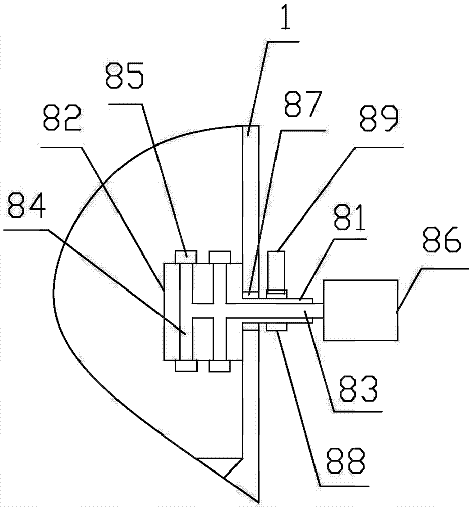
[0033]Further improvement on the basis of Example 1, the aerator 8 includes a sleeve 81, a housing 82, an intake manifold 83, an intake branch pipe 84 and a nozzle 85, and the sleeve 81 runs through the cylinder 1 and installed on the inner wall of the cylinder 1; the end of the casing 81 protruding into the cylinder 1 is provided with a housing 82, and the housing 82 is provided with a number of nozzles 85; the air intake manifold 83 Stretch into the sleeve pipe 81 to the housing 82, and be connected with the input end of the air compressor 86 at the input end of the air intake manifold 83, the output end of the intake manifold 83 located in the housing 82 is connected with some intake branch pipes 84 The input end is connected, and the output end of the intake branch pipe 84 is connected with the nozzle 85 . The sleeve 81 is rotatably connected to the inner wall of the cylinder 1 through a bearing 87; the sleeve 81 is located on the side wall of the pipe section outside the ...

Embodiment 3

[0035] As a further improvement on the basis of Embodiment 2, along the direction from one end close to the water inlet pipe 2 to one end away from the water inlet pipe 2, the heights of the several baffles 5 gradually decrease. The inner wall of the cylinder 1 is provided with a first mounting plate 11 and a second mounting plate 12 along the circumferential ring, the first mounting plate 11 and the second mounting plate 12 have an L-shaped cross-section along the axial direction of the cylinder 1, and the The settling plate 4 is pressed and fixed between the first mounting plate 11 and the second mounting plate 12 , and both the first mounting plate 11 and the second mounting plate 12 are detachably mounted on the inner wall of the barrel 1 by bolts. The first mounting plate 11 and the second mounting plate 12 are provided with sealing grooves 13 along the circumferential ring on the surface of the contacting plate of the settling plate 4, and the lower plate surface of the s...


PUM


Abstract

The invention discloses a modular sewage treatment system. A water inlet pipe is arranged on an axial top end face of a barrel body and a water discharging pipe is arranged on an axial bottom end sidewall of the barrel body; a settlement plate is arranged between the water inlet pipe and the water discharging pipe in the barrel body; a plurality of baffle plates are arranged on the settlement plate; plate surfaces of the baffle plates are vertical to the plate surface of the settlement plate; a through hole is formed in one end, far away from the water inlet pipe, on the settlement plate; thedirection of the plate surfaces of the baffle plates is vertical to the flowing direction of sewage on the settlement plate; a submersible electric pump is arranged on the water discharging pipe in the barrel body; an input end of the submersible electric pump is communicated with the inner part of the barrel body below the settlement plate and an output end of the submersible electric pump is communicated with the water discharging pipe; an aerator is further arranged on an inner wall of the barrel body located below the settlement plate; a thread connection pipe is arranged at an opening end of a conical body structure at the bottom of the barrel body; a collection barrel sleeves on the thread connection pipe through a thread. Sewage treatment equipment is arranged between a water discharging opening of factory water discharging equipment and an underground pipeline and is used for carrying out primary treatment on sewage, so that the blocking of the underground pipeline can be effectively prevented.

Description

technical field [0001] The invention relates to sewage treatment equipment, in particular to a modular sewage treatment system. Background technique [0002] Industrial sewage treatment refers to the operation that the water used in the industrial production process is properly treated and returned to production or properly discharged from the factory. The sewage in the existing production plant is directly discharged through the underground pipeline to the sewage treatment equipment for centralized treatment. For the case where the sewage contains a lot of sediment, silt or large suspended particles, if it is directly discharged through the underground pipeline, it is easy to cause The underground pipeline is blocked, and the staff needs to dig the ground for maintenance, which brings inconvenience to production. Contents of the invention [0003] The technical problem to be solved by the present invention is that if the sewage contains a lot of silt, silt or large parti...

Claims


Application Information

Patent Timeline
Patent Type & Authority Applications(China)
IPC IPC(8): C02F9/04C02F101/30
CPCC02F7/00C02F1/52C02F1/72C02F2101/30
Inventor 钟浩源
Owner 四川宇科思通环保科技有限公司
Why Eureka
Try Eureka