Hybrid power coupling mechanism and control system and method

A hybrid power and coupling mechanism technology, applied in the field of control system and hybrid power coupling mechanism, can solve the problems of many shafts, high space layout requirements, and insufficient compactness, so as to improve economic performance, optimize the working area, and reduce the number of motors. volume effect

Pending Publication Date: 2018-05-04
GUANGZHOU AUTOMOBILE GROUP CO LTD
View PDF8 Cites 8 Cited by
  • Summary
  • Abstract
  • Description
  • Claims
  • Application Information

AI Technical Summary

Problems solved by technology

However, in the existing scheme, it belongs to the four-axis system, including the engine input shaft, the intermediate shaft, the drive m

Method used


Image

  • Hybrid power coupling mechanism and control system and method
  • Hybrid power coupling mechanism and control system and method
  • Hybrid power coupling mechanism and control system and method

Examples


Embodiment Construction

[0067] The following will clearly and completely describe the technical solutions in the embodiments of the present invention with reference to the accompanying drawings in the embodiments of the present invention. Obviously, the described embodiments are only part of the embodiments of the present invention, not all of them. Based on the embodiments of the present invention, all other embodiments obtained by persons of ordinary skill in the art without making creative efforts belong to the protection scope of the present invention.

[0068] Here, it should also be noted that, in order to avoid obscuring the present invention due to unnecessary details, only the structures and / or processing steps closely related to the solution according to the present invention are shown in the drawings, and the related Other details are not relevant to the invention.

[0069] The following will clearly and completely describe the technical solutions in the embodiments of the present inventio...


PUM


Abstract

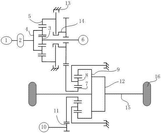
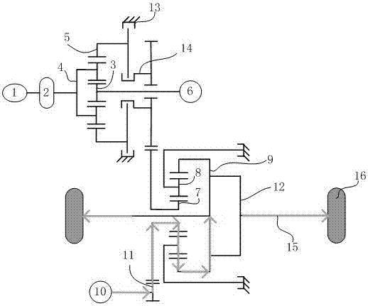
The invention discloses a hybrid power coupling mechanism. The hybrid power coupling mechanism comprises two motors, two planetary lines and a shaft tooth system, wherein an engine is connected with aplanet carrier of the first planetary line; a generator is connected with a sun gear of the first planetary line; a brake and a clutch are arranged on the first planetary line; and by reasonable control over the brake and the clutch, a range extending driving mode can be realized. A driving motor is connected with a sun gear of the second planetary line, a planet carrier of the second planetary line is fixed, and an inner gear ring of the second planetary line outputs. The invention further discloses a corresponding control system and method. By an embodiment of the invention, various drivingmodes including a pure electric mode, a range extending driving mode and a hybrid power mode and the like can be realized, only three shafts are required, the structure is compact, and requirements for space are reduced.

Description

technical field [0001] The invention relates to the field of hybrid electric vehicles, in particular to a hybrid coupling mechanism, a control system and a method. Background technique [0002] The powertrain consists of the engine (internal combustion engine) and a drive train consisting of a transmission, differential and drive shaft. Its function is to provide the vehicle with the driving power required to drive the wheels. Internal combustion engines have a range of speeds and torques, and they work best within a small range where either fuel consumption is minimized, harmful emissions are minimized, or both. However, the actual road conditions are ever-changing, not only in the speed of the driving wheels, but also in the torque required by the driving wheels. Therefore, it is the primary task of the transmission to realize the optimal speed and torque of the internal combustion engine, that is, the optimal state of power, and a good match with the power state of the ...

Claims


Application Information

Patent Timeline
IPC IPC(8): B60K6/365B60K6/442B60W20/20
CPCB60W20/20B60K6/365B60K6/442Y02T10/62
Inventor 黄河徐向阳刘艳芳赵江灵董鹏吴为理林济余王川
Owner GUANGZHOU AUTOMOBILE GROUP CO LTD
Why Eureka
Try Eureka