
Water treatment device and system and water treatment method

A technology of water treatment device and treatment chamber, which is applied in the field of water treatment, can solve problems such as difficult ultrasonic cavitation and hydraulic cavitation, and can not realize Venturi tube ultrasonic cavitation and hydraulic cavitation, etc., to achieve large-scale industrial application , work stability, cost reduction effect

Active Publication Date: 2018-05-04
INST OF ACOUSTICS CHINESE ACAD OF SCI
View PDF4 Cites 8 Cited by
  • Summary
  • Abstract
  • Description
  • Claims
  • Application Information

AI Technical Summary

Problems solved by technology

In the prior art, although there is a structure similar to the Venturi tube, the coupling of ultrasonic cavitation and hydraulic cavitation inside the Venturi tube cannot be realized. Generally, the hydraulic cavitation that occurs inside the Venturi tube-shaped flow channel generally occurs in the However, because the Venturi tube is generally a circular tubular structure, the hydraulic cavitation cloud formed is a ring structure. It is difficult to achieve the coupling of ultrasonic cavitation and hydraulic cavitation by traditional methods. We use thin-layer Venturi The inner pipe and the control of the water flow rate through the valve can solve this problem very well

Method used


Image

  • Water treatment device and system and water treatment method
  • Water treatment device and system and water treatment method
  • Water treatment device and system and water treatment method

Examples


Embodiment Construction

[0023] The technical solutions of the present invention will be described in further detail below with reference to the accompanying drawings and embodiments.

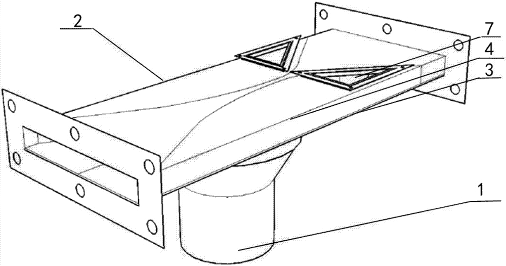
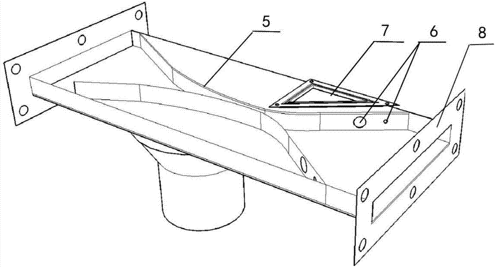
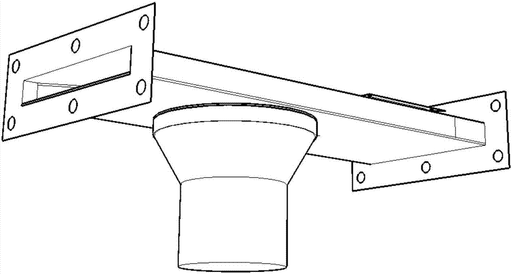
[0024] figure 1 Schematic diagram of the structure of the water treatment device provided for the embodiment of the present invention, such as figure 1 As shown, the device includes: an ultrasonic transducer 1 and a thin-layer processing chamber 2, the thin-layer processing chamber 2 contains liquid, and the thin-layer processing chamber 2 is provided with a first cover plate 3 and a second cover plate 4, The second cover plate is provided with two triangular holes 7 . Wherein, the distance between the first cover plate and the second cover plate is 1 mm˜5 cm. The radiating surface of the ultrasonic transducer is inserted into the first cover, and sealed and fixed by the rubber ring; or, the radiating surface of the ultrasonic transducer is glued to the first cover.

[0025] The ultrasonic transducer is a cleaning t...


PUM


Abstract

The invention relates to a water treatment device and system and a water treatment method. The device comprises an ultrasonic transducer and a thin-layer treatment chamber, wherein the thin-layer treatment chamber is provided with a first cover plate, a second cover plate and a tapered and gradually-enlarged flow channel; the tapered and gradually-enlarged flow channel is provided with one or morevalves; liquid is remained between the first cover plate and the second cover plate; a radiation surface of the ultrasonic transducer is fixed on the first cover plate; the ultrasonic transducer is used for emitting ultrasonic waves; the thin-layer treatment chamber is used for receiving the ultrasonic waves and generating ultrasonic cavitation; the tapered and gradually-enlarged flow channel isused for generating hydraulic cavitation; the hydraulic cavitation and the ultrasonic cavitation are coupled to grenade coupling cavitation; the coupling cavitation is used for treating water. According to the water treatment device provided by the invention, the washing groove type ultrasonic transducer is adopted and the diameter of the radiation surface is greater than that of a piezoelectric sheet, so that the device has the advantages of low price, stability in working and strong adaptability; a large radiation area covers a coupling region and an external region with an independent ultrasonic effect, so that wastes of ultrasonic energy are avoided.

Description

technical field [0001] The invention relates to the field of water treatment, in particular to a water treatment device, system and water treatment method. Background technique [0002] Contemporary China is facing enormous pressure of environmental degradation while its economy is developing rapidly, among which the problem of water pollution is particularly serious, and the current situation is worrying. Traditional chemical sewage treatment technology will bring secondary pollution, and some organic substances that are difficult to degrade cannot be degraded by traditional methods, or even if they can be degraded, the cost is very high. The physical method of sewage treatment will not produce secondary pollution, and it is a green water treatment technology. Cavitation sewage treatment technology is a physical method of sewage treatment technology. It uses the cavitation effect to generate high temperature and high pressure inside the cavity, and the hydroxyl radicals ge...

Claims


Application Information

Patent Timeline
Patent Type & Authority Applications(China)
IPC IPC(8): C02F1/36C02F1/34
CPCC02F1/34C02F1/36
Inventor 白立新吴鹏飞何北星李超苏畅张秀梅张澄宇
Owner INST OF ACOUSTICS CHINESE ACAD OF SCI
Learn More