Control method and system of photovoltaic inverter Boost circuit

A photovoltaic inverter and control method technology, applied in control/regulation systems, photovoltaic power generation, instruments, etc., can solve the problems of the converter not considering the operating state, prone to system resonance, and control parameters mismatch.

Active Publication Date: 2018-05-04
爱士惟科技股份有限公司
View PDF4 Cites 8 Cited by
  • Summary
  • Abstract
  • Description
  • Claims
  • Application Information

AI Technical Summary

Problems solved by technology

[0005] from figure 2 It can be seen that, although the voltage and current double closed-loop control method is adopted, due to the signal v pv Appearing in the inner and outer loops at the same time, resulting in a strong coupling relationship between the current inner loop and the voltage outer loop, which not only increases the difficulty of regulator design, but also tends to cause system resonance, which cannot eff

Method used


Image

  • Control method and system of photovoltaic inverter Boost circuit
  • Control method and system of photovoltaic inverter Boost circuit
  • Control method and system of photovoltaic inverter Boost circuit

Examples


Embodiment

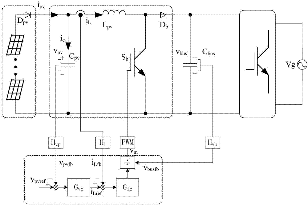
[0158] A specific example is given below to illustrate the impact of the feedforward regulator on system performance, and its main parameters are as follows:

[0159] Photovoltaic array MPP point voltage V pv = 200V;

[0160] Grid voltage V g =230V;

[0161] Rated input current I pv = 15A;

[0162] Switching frequency f s = 20kHz;

[0163] Filter inductance L pv =0.78mH;

[0164] Input capacitance C pv = 14μF;

[0165] Transfer function of photovoltaic array and DC bus voltage signal sampling conditioning circuit

[0166] Inductor current signal sampling conditioning circuit transfer function

[0167] A programmable photovoltaic array simulation source is used to simulate the actual photovoltaic array, and the MPP point voltage is set to 200V; at the same time, a programmable AC power supply is used to simulate the public grid voltage, and the grid voltage is set to V g =230V, the sine degree is good.

[0168] The inverters all work stably, effectively verifyi...


PUM


Abstract

The invention discloses an improved control method and system of a photovoltaic inverter Boost circuit. The control method of the photovoltaic inverter Boost circuit includes the following steps of obtaining a photovoltaic array voltage feedback signal vpvfb, a direct current bus voltage feedback signal vbusfb and an inductive current feedback signal iLfb; obtaining a voltage error signal the value of which is equal to a photovoltaic array voltage reference value vpvref minus the value of the voltage feedback signal vpvfb, making the voltage error signal passes through a voltage loop adjusterGvc to obtain an inductive current reference signal iLref, and substituting the inductive current reference signal iLref and the inductive current feedback signal iLfb into a current loop adjuster Gicto obtain a regulating signal vc1; substituting the voltage feedback signal vpvfb, the direct current bus voltage feedback signal vbusfb and a modulating signal vm of a last switching period into a feedforward adjuster Gff for processing to obtain a regulating signal vc2; adding the regulating signals vc1 and vc2 to obtain a new modulating signal vm, and sending the signal vm into a PWM generatorto generate a PWM driving signal of a Boost switching pipe.

Description

technical field [0001] The invention relates to the field of photovoltaic inverter Boost circuit control, in particular to a control method and system for a photovoltaic inverter Boost circuit. Background technique [0002] Distributed power generation systems represented by wind energy and solar energy, as one of the main ways of renewable energy utilization, can not only dominate the economic operation of the existing power grid, but also be clean and environmentally friendly, and their application proportion in the power system is increasing day by day. Boost converter is a step-up circuit converter with a simple structure and a wide range of applications. It is widely used in photovoltaic inverters of various power levels to adjust the output voltage of photovoltaic arrays and realize maximum power point tracking (MPPT). . Stable DC voltage control and good MPP tracking are crucial to the safe, stable, efficient and economical operation of the inverter. Therefore, how ...

Claims


Application Information

Patent Timeline
IPC IPC(8): H02M3/157
CPCY02E10/56H02M3/157
Inventor 李小龙廖小俊舒成维吴招米
Owner 爱士惟科技股份有限公司
Why Eureka
Try Eureka