Device for detecting initial rotor position of PMSM (permanent-magnet synchronous motor)

A technology of permanent magnet synchronous motor and rotor initial position, which can be used in the control of electromechanical transmission, generator control, motor control, etc., and can solve the problems of dependence, low precision, and complex implementation.

Active Publication Date: 2018-05-04
CHAJNA MAJNING DRAJVS EHND AUTOMEHJSHN KO
View PDF6 Cites 3 Cited by
  • Summary
  • Abstract
  • Description
  • Claims
  • Application Information

AI Technical Summary

Problems solved by technology

The rotor micro-movement method injects voltage space vectors at different positions in a short time, and detects the rotor motion direction according to the position sensor, and gradually approaches to calculate the initial rotor position. However, the control accuracy of this method depends on the moment of inertia of the mechanical shaft. When the mechanical When the moment of inertia increases, the initial position detection accuracy drops significantly
The high-frequency voltage injection method injects high-frequency voltage into the motor stator, and calculates the initial position of the rotor according to the mathematical model of the motor. This method depends on the motor parameters and is complicated to implement.
The pulse voltage injection method calculates the initial position of the rotor by injecting voltage space vectors in different directions and designing a reasonable current criterion. In the prior art, in the invention patent with application number 201510916273.5, the The d-axis current amplitude in the hypothetical coordinate system calculated from the size and the angle of the injected voltage vector can determine the initial position of the rotor, and ensure that the motor remains stationary during the initial position detection process by adjusting the amplitude of the injected voltage space vector, but this The detection accuracy of the method depends on the saliency rate and saturation characteristics of the motor and the accuracy of the current sensor, and is affected by the zero drift of the current sampling device. For permanent magnet motors with low precision, small saliency rate and wide unsaturated region However, the detection accuracy of the initial position of the rotor is not high by this method.
In view of the unsatisfactory initial position detection methods in the prior art, there is an urgent need for a new solution to solve this technical problem

Method used


Image

  • Device for detecting initial rotor position of PMSM (permanent-magnet synchronous motor)
  • Device for detecting initial rotor position of PMSM (permanent-magnet synchronous motor)
  • Device for detecting initial rotor position of PMSM (permanent-magnet synchronous motor)

Examples


Embodiment 1

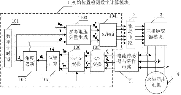
[0043] Embodiment 1: as figure 1 As shown, a rotor initial position detection device of a permanent magnet synchronous motor includes an initial position detection digital calculation module 1, a drive circuit 2, a three-phase inverter module 3, a permanent magnet synchronous motor 4, a current sensor and a sampling circuit 5, the The driving circuit 2 receives the signal of the initial position detection digital calculation module 1, generates the driving signal of the IGBT,

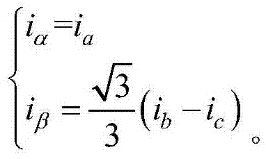
[0044] The three-phase inverter module 3 controls the upper and lower bridge arm IGBTs of each phase to be turned on and off according to the drive signal generated by the drive circuit 2, and the three-phase stator of the permanent magnet synchronous motor 4 is connected to the three-phase inverter The current sensor and the sampling circuit 5 collect the a, b and c three-phase stator currents (ia, ib and ic) of the permanent magnet synchronous motor 4.

[0045] Described initial position detection di...


PUM


Abstract

The invention relates to a device for detecting initial rotor position of a PMSM (permanent-magnet synchronous motor). The device comprises an initial position detection digital computation module, adriving circuit, a three-phase inverter module, the PMSM and a current sensor and sampling circuit, wherein the driving circuit receives signals of the initial position detection digital computation module 1 and generates IGBT driving signals; the three-phase inverter module controls IGBTs of upper and lower bridge arms of each phase to be switched on and switched off according to the driving signals generated by the driving circuit; a three-phase stator of the PMSM is connected with the three-phase inverter module; the current sensor and sampling circuit acquires currents ia, ib and ic of thea, b and c three-phase stator of the PMSM. Influence of salient rate and saturation characteristic of a motor, precision of a current sensor and zero drift of a current sampling device on positioningaccuracy is reduced greatly, and the precision for detecting the initial rotor position is improved effectively.

Description

technical field [0001] The invention relates to a detection device, in particular to a rotor initial position detection device of a permanent magnet synchronous motor, belonging to the technical field of permanent magnet synchronous motor control. Background technique [0002] Permanent magnet synchronous motors have high operating efficiency, high power density, and excellent control performance, and are widely used in electric vehicles, elevators, mine hoists, wind power generation and other electric drive fields. [0003] Obtaining the rotor position of the permanent magnet synchronous motor is one of the necessary conditions for high-performance speed regulation. In the actual permanent magnet synchronous motor speed regulation system, two methods are mainly used to obtain the rotor position. One is by installing a rotor position sensor at the motor shaft end, such as Hall sensor, incremental photoelectric encoder, absolute photoelectric encoder, resolver, etc. The seco...

Claims


Application Information

Patent Timeline
Patent Type & Authority Applications(China)
IPC IPC(8): H02P21/32H02P21/18
CPCH02P21/18H02P21/32H02P2203/03
Inventor 谭国俊吴翔李浩杨波刘光辉马凯
Owner CHAJNA MAJNING DRAJVS EHND AUTOMEHJSHN KO
Why Eureka
Try Eureka