Establishment method, establishment device, and manufacturing system for 3D porous support model

A porous scaffold and scaffold model technology, applied in the medical field, can solve the problems that cannot provide biomechanical properties and microenvironment for cell growth, cannot realize the porous structure of cancellous bone, and achieve the effect of migration

Inactive Publication Date: 2018-05-08
SHENZHEN INST OF ADVANCED TECH
View PDF10 Cites 13 Cited by
  • Summary
  • Abstract
  • Description
  • Claims
  • Application Information

AI Technical Summary

Problems solved by technology

The current method of preparing porous scaffolds is not ideal. Although the appearance can meet the personalized shape of the lesion and defect area, it cannot realize the porous structure ...

Method used


Image

  • Establishment method, establishment device, and manufacturing system for 3D porous support model
  • Establishment method, establishment device, and manufacturing system for 3D porous support model
  • Establishment method, establishment device, and manufacturing system for 3D porous support model

Examples


no. 1 example

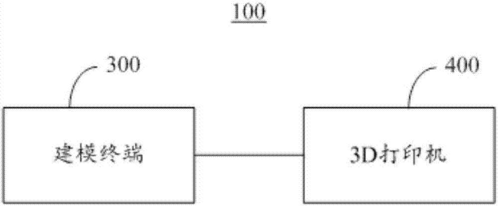
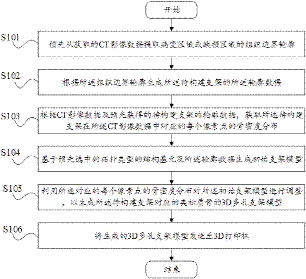
[0031] Please refer to image 3 , is the application provided by the preferred embodiment of the present invention figure 1 The flow chart of the method for building a 3D porous scaffold model of the modeling terminal 300 is shown. The method for establishing a 3D porous support model comprises the following steps:

[0032] Step S101, extracting the tissue boundary contour of the lesion area or defect area from the acquired CT image data in advance.

[0033] The above CT image data may be directly received by the modeling terminal 300 from the CT image acquisition device, or may be imported into the modeling terminal 300 in advance. The CT image data may include CT image data of the affected side area and CT image data of a side area symmetrical to the affected side area with respect to the central axis of the human body. For example, if the affected area is located in the left knee, the acquired CT image data may include CT image data of the left knee area and CT image dat...

no. 2 example

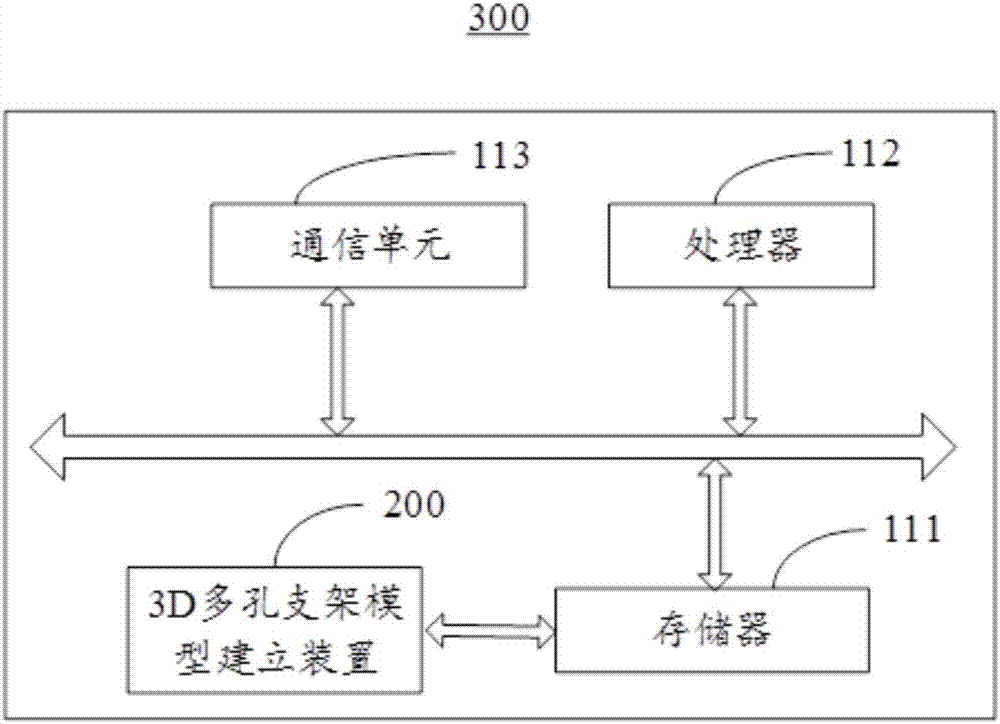
[0062] Please refer to Figure 8 , is the application provided by the preferred embodiment of the present invention figure 1 The 3D porous scaffold model building device 200 of the modeling terminal 300 shown includes: an extraction module 201 , a generation module 202 , an acquisition module 203 , a construction module 204 and an adjustment module 205 .

[0063] An extraction module 201, configured to extract tissue boundary contours of diseased areas or defect areas from the CT image data.

[0064] In the embodiment of the present invention, the step S101 may be executed by the extracting module 201 .

[0065] The generation module 202 is configured to generate the contour data of the scaffold to be constructed according to the tissue boundary contour.

[0066] In the embodiment of the present invention, the step S102 may be executed by the generation module 202 .

[0067] The acquisition module 203 is configured to acquire the bone density distribution of each pixel corr...


PUM


Abstract

The invention provides an establishment method, an establishment device, and a manufacturing system for a 3D porous support model, and relates to the technical field of medical science. The establishment method for a 3D porous support model comprises: according to CT image data of skeleton lesion or defect positions, obtaining outline data of a to-be-established support and bone mineral density distribution of each corresponding pixel point of the to-be-established support in the CT image data, selecting an element of a topological structure type in minimum structure, and based on the selectedtopological type structure element and the outline data, generating an uniform porosity initial support model, using the corresponding bone mineral density distribution of each pixel point, adjustingthe porosity of each structure element and micropore size in the initial support model, to generate a 3D porous support model like cancellous bone corresponding to the to-be-established support. A porous support printed according to the 3D porous support model like cancellous bone satisfies a bionic microstructure having biomechanical characteristics on bone defect positions, and satisfies cell migration, differentiation, and multiplication and other cell growth microenvironment.

Description

technical field [0001] The invention relates to the field of medical technology, in particular to a method, device and preparation system for establishing a 3D porous scaffold model. Background technique [0002] In the field of orthopedics, bone lesions and defects due to severe trauma, bone tumors, osteomyelitis and other reasons are very common. Currently commonly used bone repair materials include autogenous bone and metal prosthesis. Autogenous bone increases the trauma and pain of patients; metal prosthesis has problems such as loosening and stress shielding. Therefore, repairing bone defects with artificial bone substitute materials has become a medical focus. Preparation of bioactive porous scaffolds to be implanted in defective parts of the body can provide carriers for cell growth, proliferation and differentiation, and form new tissues or organs that are compatible with their own functions and anatomical forms, so as to achieve the purpose of repairing or improv...

Claims


Application Information

Patent Timeline
IPC IPC(8): A61F2/28B33Y70/00B33Y80/00B33Y10/00
CPCA61F2/2846B33Y10/00B33Y70/00B33Y80/00
Inventor 白雪岭
Owner SHENZHEN INST OF ADVANCED TECH
Why Eureka
Try Eureka