
Method for sewing and integrally forming metal member and composite material

A technology for metal components and composite materials, which is applied in the field of stitching and integral molding of metal components and composite materials, can solve the problems of difficulty in mold design and process manufacturing, failure of fiber continuity of composite materials, and failure of composite material structures, and achieves good promotion. The effect of application value, simplifying the forming process, and improving product quality

Active Publication Date: 2018-05-08
AEROSPACE INST OF ADVANCED MATERIALS & PROCESSING TECH
View PDF6 Cites 0 Cited by
  • Summary
  • Abstract
  • Description
  • Claims
  • Application Information

AI Technical Summary

Problems solved by technology

However, the more complex the composite material component, the more difficult it is to design and manufacture the mold
Composite materials that are formed in separate parts are connected into a whole by gluing, screwing or riveting, which can reduce the difficulty of forming, but the connection methods such as riveting and screwing will cause damage to the composite material structure, and the performance of the structural parts is lower than that of the composite material. Integral molded composite structure
[0003] In the preparation process of composite products, most of them need to involve the connection of composite materials and metals. The traditional process method adopts rivet assembly for connection. The use of a large number of rivets not only increases the weight and process cost of the product, but also leads to composite materials. The fiber continuity of the material is destroyed, resulting in many problems such as damage around the assembly hole or the need for reinforcement, which directly affects the bearing capacity of the airfoil

Method used

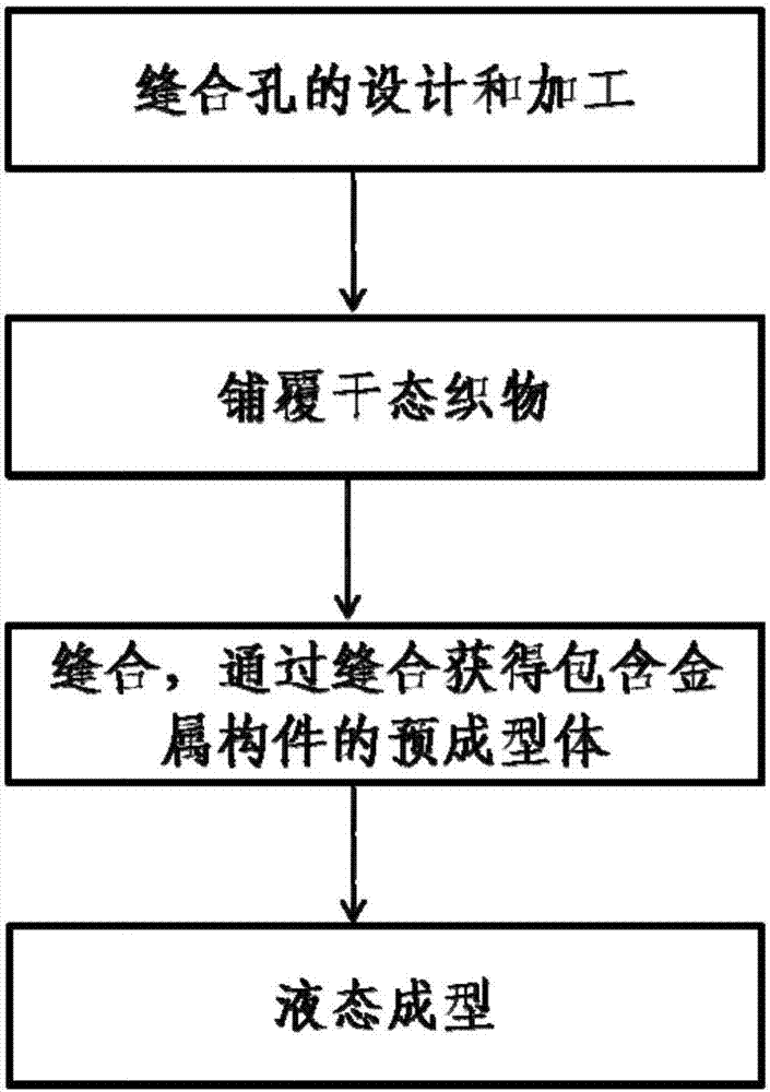

Image

  • Method for sewing and integrally forming metal member and composite material
  • Method for sewing and integrally forming metal member and composite material
  • Method for sewing and integrally forming metal member and composite material

Examples


preparation example Construction

[0038] (2) Paste the adhesive film on the seamed area of ​​the metal member, and then spread the dry fabric on the upper surface and / or lower surface of the metal member. Wherein, used dry state fabric can select fiber cotton, fiber felt, fiber blanket, fiber cloth etc., and preparation method can adopt existing processing method, for example needle punching molding process. The fiber cloth can be any one of unidirectional carbon cloth, plain carbon cloth or satin carbon cloth. Unidirectional carbon cloth is a kind of dry carbon fiber cord fabric. The fabric structure is similar to plain carbon cloth, but there are only very thin glass filaments in the weft direction, and the weft direction glass filaments play a role in maintaining the shape of unidirectional carbon cloth. After laying is complete, the dry fabric is styled. The setting method can select any one of the spraying setting agent method (the surface spraying of the dry fabric has a viscous setting agent), the migr...

Embodiment 1

[0043] Preparation thickness is the composite material product of 6mm, wherein the laying thickness of composite material on the upper surface and the lower surface of the aluminum alloy plate is 2mm, and the metal component is an aluminum alloy plate, and the thickness is 2mm.

[0044] (11) Design and processing of suture holes

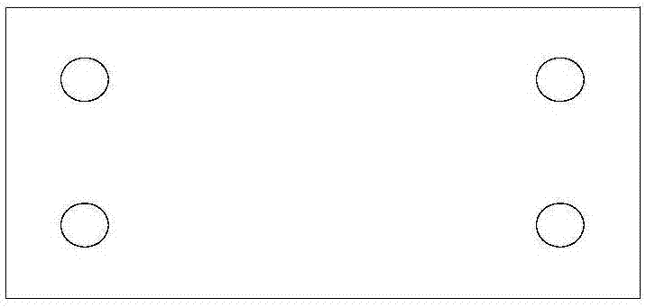
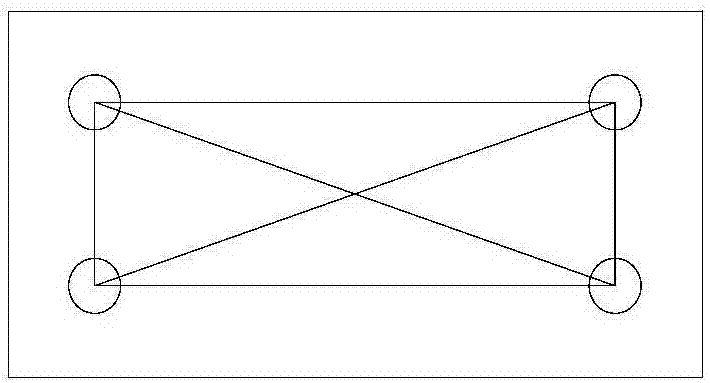
[0045] Such as figure 2 As shown, a positioning hole is opened at the four corners of the metal component, the metal component is bonded over the entire area, and the area S is 80mm*15mm=1200mm 2 , area positioning coefficient k 0 is 0.024, the total area S of the suture holes designed on the metal member 0 =k 0 S=28.8mm 2 , the diameter of the suture hole is 3mm, the edge distance of the hole is 5mm, and the hole edge distance coefficient of the suture hole is k 1 is 1.67. Horizontal hole spacing d 2横 30mm, hole spacing factor k 2 10; longitudinal hole spacing d 2纵 5mm, hole spacing factor k 2 is 1.67. Sulfuric acid anodizing treatment i...

Embodiment 2

[0053] Prepare a 6mm composite material product, wherein the composite material is 2mm up and down, and the metal component is an aluminum alloy plate with a thickness of 2mm.

[0054] (21) Design and processing of suture holes

[0055] Such as figure 2 As shown, a positioning hole is opened at the four corners of the metal component, the metal component is bonded over the entire area, and the area S is 80mm*15mm=1200mm 2 , area positioning coefficient k 0 is 0.01, the total area S of the suture holes designed on the metal member 0 =k 0 S=12mm 2 , the diameter of the suture hole is 2mm, the edge distance of the hole is 2mm, and the hole edge distance coefficient of the suture hole is k 1 is 1. Horizontal hole spacing d 2横 30mm, hole spacing factor k 2 15; longitudinal hole spacing d 2纵 11mm, hole spacing factor k 2 is 5.5. Sulfuric acid anodizing treatment is performed on the surface of the aluminum alloy plate.

[0056] (22) Cover dry fabric

[0057] First, stic...


PUM

PropertyMeasurementUnit
thicknessaaaaaaaaaa

Abstract

The invention relates to a method for sewing and integrally forming a metal member and a composite material. The method comprises the following steps that sewing holes for sewing are machined in a sewing area of the metal member, the total area S0 of the sewing holes is equal to k0S, S is the area of the sewing area of the metal member, and k0 is larger than or equal to 0.01 and smaller than or equal to 0.1; the hole side distance d1 of the sewing holes is equal to k1d, and the hole spacing distance d2 of the sewing holes is equal to k2d; d is the diameter of the sewing holes, k1 is larger than or equal to 1 and smaller than or equal to 12, and k2 is larger than or equal to 1.5 and smaller than or equal to 15; a glue film is attached to the sewing area of the metal member, dry fabric is laid on the upper surface and / or the lower surface of the metal member, then the dry fabric is shaped, and finally the shaped dry fabric is compacted; sewing is carried out, and a preformed body is obtained; and the liquid forming technology is adopted, and a composite material product with the metal member is manufactured. According to the method, secondary machining and riveting working proceduresare not needed, the forming working procedure is simplified, the cost is reduced, and the product quality is improved.

Description

technical field [0001] The invention relates to the technical field of composite materials, in particular to a method for sewing and integrally forming metal components and composite materials. Background technique [0002] Resin-based composite materials are widely used in the aerospace field for main load-bearing parts such as wings and wing structures due to their high specific stiffness, specific strength, and corrosion resistance. At present, the forming of composite material structure basically adopts the method of integral forming and split forming machine. The advantages of integral molding of composite materials are that each structural component can transmit load evenly, reduce the number of parts, and reduce assembly costs. However, the more complex the composite material component is, the more difficult it is to design and manufacture the mold. Composite materials that are formed in separate parts are connected into a whole by gluing, screwing or riveting, whic...

Claims


Application Information

Patent Timeline
Patent Type & Authority Applications(China)
IPC IPC(8): B29C70/40B29C70/54B29C70/68B29B11/16B29L31/30
CPCB29B11/16B29C70/40B29C70/54B29C70/682B29C70/683B29L2031/3085
Inventor 卢山许亚洪龚文化张明韩蕾武海生
Owner AEROSPACE INST OF ADVANCED MATERIALS & PROCESSING TECH
Learn More