
LNG cold energy gradient utilization method for conducting power generation by adopting cold energy

A cold energy and cascade technology, applied in the field of cascaded utilization of LNG cold energy using cold energy to generate electricity, can solve the problems of unreasonable utilization of cold energy, reduced effect of cold energy utilization, and large losses, so as to improve energy utilization efficiency and improve Cooling recovery rate, effect of reducing vaporization cost

Inactive Publication Date: 2018-05-08
SICHUAN JINYING TECH CO LTD
View PDF5 Cites 10 Cited by
  • Summary
  • Abstract
  • Description
  • Claims
  • Application Information

AI Technical Summary

Problems solved by technology

At present, in the utilization of cold energy of LNG, there are low utilization efficiency of cold energy, Due to the large loss phenomenon, most of the cold energy carried by LNG has not been rationally utilized
[0006] At present, the design of some cascade cold energy utilization processes lacks strong theoretical arguments, or there is a disconnect between theory and actual utilization. The cascade utilization of LNG cold energy is only studied from the perspective of energy, while the quality of LNG cold energy is ignored, resulting in the actual Cold storage of LNG utilization process in utilization The efficiency is very low, and there is a phenomenon that the cold energy of LNG has not been reasonably and fully utilized. The high-quality cold energy in the lower temperature range is used in a process that requires low cold energy grades, resulting in a significant reduction in the use of cold energy
[0007] Although the cascade cold energy utilization process has been proposed, it still has not been able to fundamentally solve the problems of low utilization efficiency and low economic benefits of LNG cold energy

Method used


Image

  • LNG cold energy gradient utilization method for conducting power generation by adopting cold energy
  • LNG cold energy gradient utilization method for conducting power generation by adopting cold energy
  • LNG cold energy gradient utilization method for conducting power generation by adopting cold energy

Examples


Embodiment 1

[0068] like Figure 10 Shown, adopt the LNG cold energy cascade utilization method of cold energy power generation, it comprises the following steps:

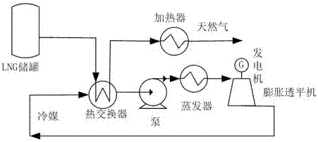
[0069] S1. Use LNG cold energy to generate electricity through direct expansion method, secondary media method or combined method;

[0070] S2. Use the cold energy of LNG after power generation to crush waste rubber at low temperature;

[0071] S3. Utilize the cold energy of LNG after the waste rubber is pulverized at low temperature to cool the warehouse.

[0072] According to the thermodynamic calculation method, the process The loss calculation process is as follows:

[0073] ①Cold power generation

[0074] It can be seen from the above process that: T 0 =193K; R=0.520kJ / (kmol·K);

[0075] T=111K; c p =2.16kJ / (kg·K);

[0076] p=0.1MPa; p 0 =0.5MPa; r=505kJ / kg.

[0077] ex stands for single stage process ; EX stands for total plan .

[0078] pressure :

[0079] ex p =T 0 RIn(p / p 0 )=193×0.520×In(0.1 / 0.5)...

Embodiment 2

[0092] like Figure 11 Shown, adopt the LNG cold energy cascade utilization method of cold energy power generation, it comprises the following steps:

[0093] S1. Use LNG cold energy to generate electricity through direct expansion method, secondary media method or combined method;

[0094] S2. Use the cold energy of LNG after power generation to crush waste rubber at low temperature;

[0095] S3. Seawater desalination is carried out by utilizing the cold energy of LNG after the waste rubber is pulverized at low temperature.

[0096] ①Cold power generation

[0097] ex p =-161.5kJ / kg; ex c,s =53.5kJ / kg; ex c,l =373.1kJ / kg; ex=265.0kJ / kg

[0098] ②Low temperature crushing and shredding of waste

[0099] ex p =-101.5kJ / kg; ex c,s =4.8kJ / kg; ex c,l =78.8kJ / kg; ex=-18.2kJ / kg

[0100] ③ Sea water desalination

[0101] ex p =131.1kJ / kg; ex c,s =18.7kJ / kg; ex c,l =147.2kJ / kg; ex=297.0kJ / kg

[0102] EX=543.8kJ / kg.

Embodiment 3

[0104] like Figure 12 Shown, adopt the LNG cold energy cascade utilization method of cold energy power generation, it comprises the following steps:

[0105] S1. Use LNG cold energy to generate electricity through direct expansion method, secondary media method or combined method;

[0106] S2. Using the cold energy of LNG after power generation to produce liquefied CO 2 and dry ice;

[0107] S3. Utilization is completed to produce liquefied CO 2 And LNG cold energy after dry ice for warehouse refrigeration.

[0108] ①Cold power generation

[0109] ex p =-197.7kJ / kg; ex c,s =31.9kJ / kg; ex c,l =282.1kJ / kg; ex=116.3kJ / kg

[0110] ② Preparation of liquefied CO 2 and dry ice

[0111] ex p =28.4kJ / kg; ex c,s =11.2kJ / kg; ex c,l =128.4kJ / kg; ex=168.0kJ / kg

[0112] ③Frozen warehouse

[0113] ex p =50.4kJ / kg; ex c,s =22.7kJ / kg; ex c,l =165.2kJ / kg; ex=238.3kJ / kg

[0114] EX=522.6kJ / kg


PUM


Abstract

The invention discloses an LNG cold energy gradient utilization method for conducting power generation by adopting cold energy. The LNG cold energy gradient utilization method comprises the followingsteps that S1, power generation is conducted by utilizing the LNG cold energy; S2, oilfield associated gas condensate recovery or preparation of liquefied CO2 and dry ice or cryogenic pulverization ofwaste rubber is conducted by utilizing the LNG cold energy which completes power generation; and S3, warehouse refrigeration or sea water desalination is conducted by utilizing the LNG cold energy which completes oilfield associated gas condensate recovery or preparation of the liquefied CO2 and the dry ice or cryogenic pulverization of the waste rubber. The LNG cold energy gradient utilization method has the beneficial effects that under the premise that the requirements of different users for the operating characteristics are met, optimal configuration of the cold energy among the multipleusers is arranged, and gradient utilization of the cold energy is achieved. A three-level utilization scheme is formulated according to the requirements of various cold energy utilization technologiesfor the temperature levels, the LNG cold energy recovery rate is increased, the LNG vaporization cost is reduced, and the LNG cold energy gradient utilization method is of great significance for saving the energy and improving the energy utilization efficiency.

Description

technical field [0001] The invention relates to the technical field of LNG cold energy utilization, in particular to a cascaded utilization method of LNG cold energy for power generation using cold energy. Background technique [0002] Since the beginning of the 21st century, the world's oil prices have soared, and energy and electricity costs have increased significantly. In the form of China's rapid economic development, it is imperative to save energy and improve energy utilization. As a clean and efficient energy source, LNG is favored by countries all over the world, which has also brought about the rapid development of the LNG industry (an average annual growth rate of 20%). [0003] LNG is a low-temperature (-162°C) liquid mixture made of low-pollution natural gas after deacidification and dehydration treatment, and freezing and liquefaction through a low-temperature process. Its density is increased by about 600 times to facilitate long-distance transportation. The ...

Claims


Application Information

Patent Timeline
IPC IPC(8): F01K11/02F01K25/10F01K23/00F25B27/02F25J1/00C01B32/55B29B17/04
CPCB29B17/0408F01K11/02F01K23/00F01K25/10F25B27/02F25J1/0027Y02A30/274Y02P20/10Y02P70/10Y02W30/62
Inventor 唐文静
Owner SICHUAN JINYING TECH CO LTD
Learn More